4
VALV
SIZE
1
“ii
1
‘z
2
2;
3
4
PRESSURE
DROP
PSI
15 [103]
10 [70]
5
r351
1
r71
.5
[3.4]
.l
1.71
1
m
2
I
ki
ii
z
iz
z
z
%
0
WC
Loo
E
[25:
Es0
,[13
El0
:[251
,5
rr1.3
_
cl
;[.25
‘.5
rj.13
:1
[.025
Ml
M2
-
140,00(
f
[3900]
,-100,00
=[2800]
zi-
?-
fi_
-
50,000
i!-
[1400]
-
500
1
u41
-200
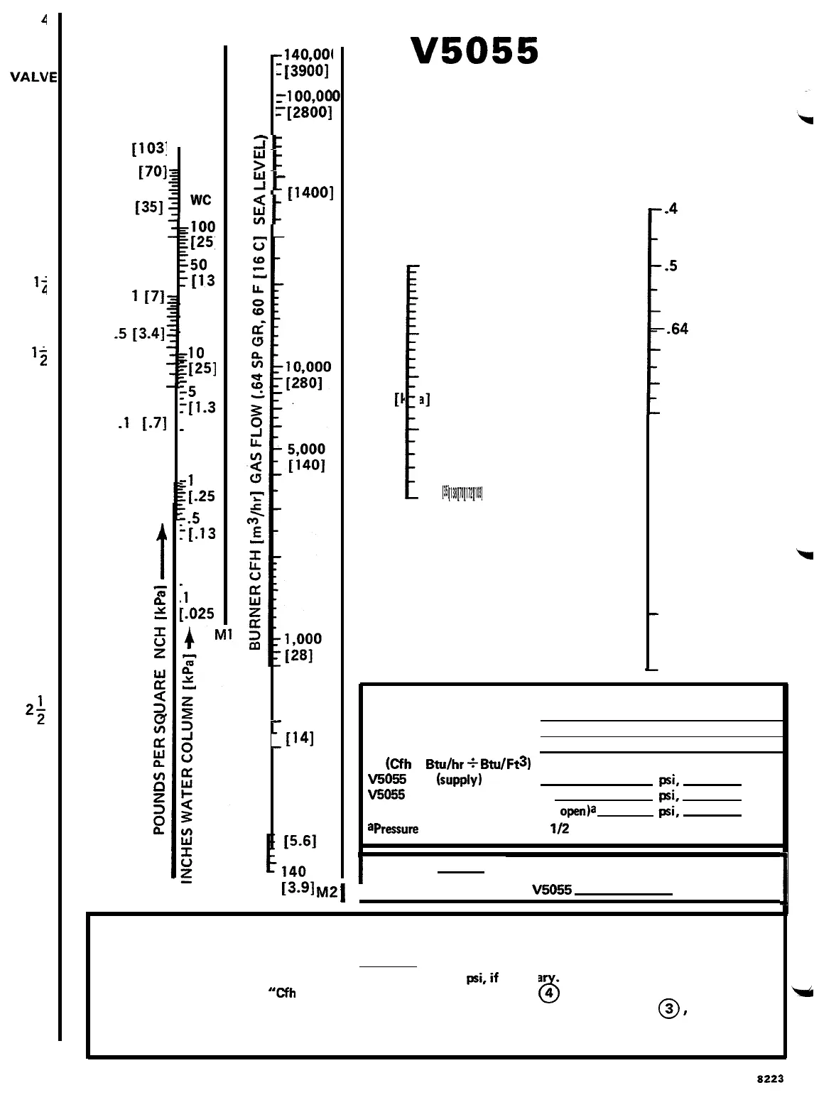
V5055
VALVE
SIZING CHART
OUTLET
PRESSURE
(PSI
[kPa]
GAUGE)
!
20 25 10 5 15 [351 [138] [70] [172] [103]
0
SPECIFIC
GRAVITY
CORRECTION
!
.4
-5
-64
-1.0
-1.5
-
2.0
-
2.5
REQUIRED INFORMATION
Type of Gas
Specific Gravity
Burner Gas Cfh
(Cfh
= Btu/hr
f
Btu/Ft3)
V5055
Inlet
(supply)
Pressure
psi,
V5055 Outlet Pressure Required
psi.
Pressure Drop across valve (valve
open)a
psi,
apressure
drop must not exceed
l/2
the inlet pressure.
in. wc
in. wc
in. wc
I
Valve Size
inches
13.91
~2
j
Ordering Specification No.
V5055
I
INSTRUCT1 ONS
NOTE: If natural gas (specific gravity 0.64) is used,
3. Draw line 3
0
from
“Outlet Pressure” to
skip steps one and two, and start with
step
three.
1. Draw line
0
“Pressure Drop.” Convert pressure from inch
WC
to
1
from 0.54 on “Specific Gravity
psi,if
necessa
.
Correction” to required “Cfh Gas Flow.”
2. Draw line
0
4. Draw line 4
6
from “Burner Cfh,” through
2
from “Specific Gravity” of gas used
0
intersection of Ml and line
@
,
to “Valve
through intersection of line 1 and M2 to get Size.” When point falls between two valve sizes,
“Burner Cfh.”
select the larger one.
14
8223
 Loading...