EasyManua.ls Logo

Honeywell V4062A User Manual

Honeywell V4062A
8 pages
To Next Page IconTo Next Page
Page #1 background imageLoading...
Page #1 background image
PRODUCT DATA
60- 2099- 9
® U.S. Registered Trademark
Copyright © 2001 Honeywell • All Rights Reserved
V4062A,B,D
HI-LO-OFF Fluid Power
Gas Valve Actuator
APPLICATION
The V4062 Gas Valve Actuator in combination with a V5055,
VE5000
a
or V5097 Gas Valve provides three-position control
of the gas supply to commercial and industrial burners.
FEATURES
When energized, the V4062 Actuator opens the
V5055/VE5000/V5097 Gas Valve to the low-fire
position. The actuator opens the valve to the fully open
position when the line voltage contacts are made.
a
VE5000 is a European manufactured and approved valve for
European use only.
When used with the V5055, V5097 or VE5000
a
Gas
Valve, the combination is rated for final safety shutoff
service.Although the V4062 can be used with all V5055
or V5097 Valve models, the V5055/V5097B with
characterized guide is recommended for optimum
control and low-fire repeatability.
The standard model has an opening time of
26 seconds at 60 Hz, or 32 seconds at 50 Hz. A
fast-opening model is available, with timings of
13 seconds at 60 Hz, or 16 seconds at 50 Hz.
Maximum closing time is one second, which meets
code, standard, insurer requirements.
Damper shaft models are available with or without
spring return; shaft extends out both sides and rides
in Delrin bushings; used with standard damper crank
arm (part no. 7616BR).
Red OPEN indicator attached to the actuator stem
shows when the valve is even slightly open; yellow
SHUT indicator on the valve stem shows only when
the gas valve is fully closed.
Ambient temperature range is -40° to 150°F (-40° to
66°C) for 60 Hz models; -10° to 158°F (23° to 70°C) for
50 Hz and 50/60 Hz models.
Models available with factory adjusted, field-
adjustable, single-pole-double throw (spdt) auxiliary
switch rated at 1/2 hp (0.37 kW). Auxiliary switch can
be added in the field.
Low-fire position is adjustable with adjusting wrench,
part no. 135796 (included with the actuator).
Standard enclosure meets NEMA 1 (IP30) general
purpose requirements.
V4062/V5055C,E and V4062/V5097C,E combinations
available with a proof-of-closure switch and double
valve seal (valve seal overtravel interlock) to meet
specific code/standard/insurer requirements.
Model available to be used with series 60 floating type
controller.
Model available with adjustable maximum flow switch.
Contents
Application ........................................................................ 1
Features ........................................................................... 1
Specifications ................................................................... 2
Ordering Information ........................................................ 2
Installation ........................................................................ 4
Wiring ............................................................................... 6
Adjustments ...................................................................... 7
Operation .......................................................................... 8
Service and Checkout ...................................................... 8
Question and Answer IconNeed help?

Do you have a question about the Honeywell V4062A and is the answer not in the manual?

Honeywell V4062A Specifications

General IconGeneral
BrandHoneywell
ModelV4062A
CategoryController
LanguageEnglish

Summary

APPLICATION

FEATURES

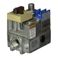
Details about the V4062 Actuator's capabilities and benefits, including its role in gas supply control.

PRODUCT DATA

SPECIFICATIONS

Models

Lists the different V4062 actuator models and their specific features and applications.

Electrical Ratings

Provides voltage and frequency ratings for various actuator configurations and opening times.

ORDERING INFORMATION

Mounting

Low-Fire Adjustment

Steps to set the minimum gas flow position for burner lightoff.

Nominal Opening Time

Specifies the time taken for the actuator to open the valve.

Closing Time

Specifies the maximum time taken for the actuator to close the valve.

Damper Shaft

Details regarding the damper shaft and its compatibility with crank arms.

Ambient Operating Temperature Rating

Defines the permissible ambient temperature range for operation.

Approvals

Lists the safety and regulatory approvals obtained for the actuator.

Accessories

Information on optional accessories available for the V4062 actuator.

INSTALLATION

Install Valve

Procedure for installing the actuator onto the gas valve body.

Install Accessory Switches (If Needed)

Instructions for adding auxiliary and proof-of-closure switches.

Mount Actuator On Valve

Specific steps for securely mounting the actuator to the valve body.

Mount and Adjust 7616BR Damper Crank Arm (If Used)

Guidance on attaching and adjusting the damper crank arm for damper control.

WIRING

ADJUSTMENTS

Low-Fire Adjustment

Steps to set the valve's minimum flow position for safe burner operation.

Recommended Procedure

A step-by-step guide for adjusting the low-fire setting before system operation.

Alternate Procedure

A method for adjusting low-fire setting while the burner is operational.

Adjust Auxiliary Switch (If Used)

How to adjust the auxiliary switch for specific operational points.

Adjust Max Flow Limit Switch

Instructions for setting the maximum flow limit switch.

OPERATION

SERVICE AND CHECKOUT

Service

Guidelines on what can and cannot be serviced in the field.

Checkout

Steps to verify proper operation after installation.

V4062A1156 Fluid Power Gas Actuator

Specific details about a modified version of the V4062 actuator.

Related product manuals