V4062A,B,D HI-LO-OFF FLUID POWER GAS VALVE ACTUATOR
60-2099—9 4
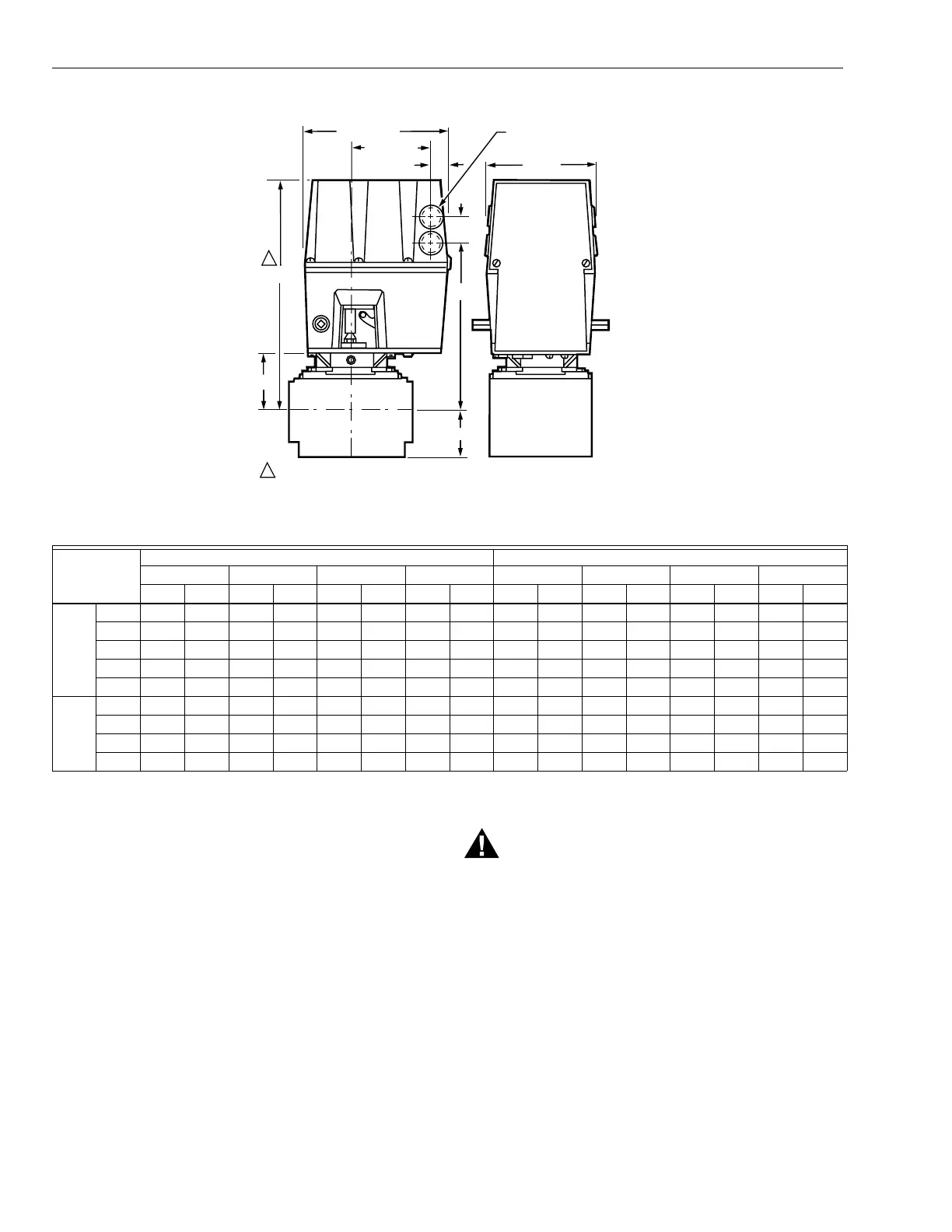
Fig. 1. Approximate mounting dimensions of V4062 Actuators in in. (mm).
Table 7. Approximate Mounting Dimensions of V4062 Actuators with V5055 and V5097 Valves.
a
Valve size using accessory pipe adapter fitting.
INSTALLATION
When Installing This Product…
1. Read these instructions carefully. Failure to follow
them could damage the product or cause a hazardous
condition.
2. Check the ratings given in the instructions and on the
product to make sure the product is suitable for your
application.
3. Installer must be a trained experienced, flame
safeguard control technician.
4. After installation is complete, check out product
operation as prided in these instructions.
WARNING
Electrical Shock Hazard.
Can cause serious injury or death.
Disconnect power supply before making wiring
connections to prevent electrical shock and
equipment damage.
IMPORTANT
1. All wiring must comply with all applicable electrical
codes, ordinances, and regulations. All wiring must be
NEC Class 1.
2. Voltage and frequency of the power supply connected to
this control must agree with those marked on the device.
3. Loads connected to the auxiliary switch and/or
proof-of-closure switch, if used, must not exceed the
ratings given in the Specifications section.
4. When replacing a V6034 Actuator with a V4062, the
V5034 Valve body must be changed to a V5055 Valve.
5. Do not attempt to use the V4062 Actuator with the
V4055/V5034 Adapter. Differences in stem travel can
prevent correct low fire adjustment.
Valve Size
a
(in.)
V5055 V5097
Dim. A Dim. B Dim. C Dim. D Dim. A Dim. B Dim. C Dim. D
in.mmin.mmin.mmin.mmin.mmin.mmin.mmin.mm
Small
Body
3/4 11-1/8 283 2-3/4 70 8-3/16 208 5-3/4 146 11-1/8 283 2-3/4 70 8-3/16 208 2-1/2 64
1 11-1/8 283 2-3/4 70 8-3/16 208 5-3/4 146 11-1/8 283 2-3/4 70 8-3/16 208 2-/12 64
1-1/4 11-1/8 283 2-3/4 70 8-3/16 208 5-3/4 146 11-1/8 283 2-3/4 70 8-3/16 208 2-1/2 64
1-1/2 11-1/8 283 2-3/4 70 8-3/16 208 5-3/4 146 11-1/8 283 2-3/4 70 8-3/16 208 2-1/2 64
2 11-1/8 286 2-7/8 73 8-5/16 211 8-3/8 213 11-3/4 298 3-3/8 86 8-3/8 213 4 102
Large
Body
2 11-3/4 298 3-3/8 86 8-13/16 224 9-1/4 235 11-3/4 298 3-3/8 86 8-3/8 213 4 102
2-1/2 11-3/4 298 3-3/8 86 8-13/16 224 9-1/4 235 11-3/4 298 3-3/8 86 8-3/8 213 4 102
3 11-3/4 298 3-38 86 8-13/16 224 9-1/4 235 11-3/4 298 3-3/8 86 8-3/8 213 4 102
4 14-1/83595-13/1614811-7/3228512-1/2318————————
D
A
1
1
(33)
KNOCKOUT FOR
1/2 INCH CONDUIT (4)
5 (127)
1-9/32
27/32 (21)
3-23/32 (95)
6-3/4 (172)
C
B
ALLOW 4 INCH (102 MM) CLEARANCE FOR ACTUATOR REMOVAL. M1775
VALVE
VALVE
 Loading...