Do you have a question about the Honeywell V800 Series and is the answer not in the manual?
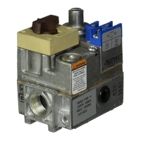
Details features and models of Super Tradeline controls for broad replacement applications.
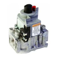
Describes Tradeline models for ease of stocking and handling, matching Super Tradeline specs.
Lists standard models, referring to Table 1 for specific model specifications.
Highlights Tradeline models featuring side outlets for easier installation.
Provides guidelines for installing gas piping, including traps and bends.
Instructions for mounting the gas control, considering orientation and pipe thread depth.
Guidance on cutting, preparing, and connecting pilot gas tubing to the control.
Details on connecting thermocouple electrical leads for specific voltage models.
Instructions for connecting the Energy Cutoff (ECO) connector for specific models.
Provides typical wiring diagram and connections for 24V models.
Instructions for wiring millivoltage-powered Powerpile models, avoiding line voltage.
Details typical wiring hookups for line voltage models using junction boxes.
Procedure for performing a gas leak test after installation or servicing.
Step-by-step instructions for safely lighting the pilot burner.
Guidance on adjusting the pilot flame size for proper thermocouple heating.
Procedure to check and adjust outlet pressure for standard regulators.
Instructions for checking and adjusting step-opening regulators.
Procedure to verify the safety shutdown functionality.
Describes the state of the control when the knob is in the OFF position.
Explains the control's state when the knob is set to PILOT.
Details the standby operation when the knob is ON, but no heat is called.
Describes operation when the thermostat calls for heat with the knob ON.
Explains how the control reacts and shuts down if the pilot flame is lost.
Details how servo pressure regulators maintain outlet gas pressure.
Troubleshooting steps for when the pilot burner fails to ignite.
Troubleshooting for pilot flame extinguishing after knob release.
Troubleshooting steps for when the main burner fails to activate.
Guidance on addressing excessive burner output.
Instructions for vacation and complete shutdown of the appliance.
| Brand | Honeywell |
|---|---|
| Model | V800 Series |
| Category | Controller |
| Language | English |