APPLICATION
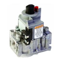
The VS820 and VS821 are used on gas fired, standing
pilot appliances with 750 mV self-powered control systems.
The gas controls include a manual gas valve, safety shutoff,
single millivoltage automatic operator and pressure regula-
tor. Refer to Table 1 for capacity ratings and Table 2 for
pressure regulators and temperature ratings. Separate
models are available for natural and LP gas; the controls
cannot be field converted.
Power for the gas control and the control system is
provided by a 750 mV Powerpile generator. We recom-
mend the Q313 Thermopile Generator or the CS82, CS893,
CS894, or CS897 Pilot Burner Generators.
TABLE 1—VS820 AND VS821 PIPE SIZE AND CAPACITY RATINGS.
INLET x OUTLET REDUCER FITTINGS
b
CAPACITY
a
CAPACITY
MODEL PIPE SIZE cfh m
3
/hr SIZE cfh m
3
/hr
VS821 1/2 x 3/8 110 3.1 — — —
VS820 1/2 x 1/2 225 6.4 — — —
1/2 x 3/4 250 7.1 3/4 x 1/2 225 6.4
1/2 x 3/8 110 3.1
3/4 x 3/4 335 9.5 3/4 x 1/2 250 7.1
3/4 x 1/2 225 6.4
VS820 1 x 1 600 17.0 1 x 3/4 503 14.2
High Capacity 1 x 3/4 450 12.7
a
Capacity is based on 1000Btuh/ft
3
, 0.64 sp gr natural gas at 1 in. wc pressure drop [37.3 MH/m
3
, 0.64 sp gr natural gas
at 0.25 kPa pressure drop]. Use conversion factors in Table 3 to convert for other gases.
b
Reducer fittings must be obtained locally.
TABLE 2—PRESSURE REGULATOR AND TEMPERATURE RATINGS.
MODEL PRESSURE REGULATOR TEMPERATURE RATING
TYPE MODEL °F °C
VS820A,H Standard V5306A 32 to 175 0 to 79
VS821A
VS820C, VS821C Step V5307A
VS820D Hi-Low V5308A
VS820P Step V5307B -40 to 175 -40 to 79
VS820V Standard V5306A
WARNING
FIRE OR EXPLOSION HAZARD
CAN CAUSE PROPERTY DAMAGE, SEVERE IN-
JURY, OR DEATH
Follow these warnings exactly:
1. Disconnect power supply before wiring to pre-
vent electrical shock or equipment damage.
2. To avoid dangerous accumulation of fuel gas,
turn off gas supply at appliance service valve
before starting installation and perform Gas
Leak Test following installation.
3. Do not bend pilot tubing at control or at pilot
after compression fitting has been tightened.
Gas leakage at the connection fitting may
result.
4. Always install sediment trap in gas supply line
to prevent contamination of gas control.
5. Do not force gas control knob. Use only your
hand to turn gas control knob. If the knob will
not operate by hand, the control should be
replaced by a qualified service technician.
Force or attempted repair may result in fire or
explosion.
INSTALLATION
WHEN INSTALLING THIS PRODUCT…
1. Read these instructions carefully. Failure to follow
them could damage the product or cause a hazardous
condition.
2. Check the ratings given in these instructions and on
the product to make sure the product is suitable for your
application.
3. Make sure installer is a trained, experienced service
technician.
4. After completing installation, use these instructions to
check product operation.
TABLE 3—GAS CAPACITY CONVERSION FACTORS.
SPECIFIC MULTIPLY
TYPE OF GAS GRAVITY LISTED CAPACITY BY
Manufactured 0.60 0.516
Mixed 0.70 0.765
Propane 1.53 1.62
D.T. Form Number 95-6994—8
Rev. 4-89 ©Honeywell Inc. 1989
VS820A,C,D,H,P,V AND VS821A,C
MILLIVOLTAGE COMBINATION
GAS CONTROLS