EasyManua.ls Logo

Honeywell VR8300 User Manual

Honeywell VR8300
10 pages
To Next Page IconTo Next Page
Page #1 background imageLoading...
Page #1 background image
1 69-0624—2
J.H. • Rev. 9-94 • ©Honeywell Inc. 1994 • Form Number 69-0624—2
VR8300/VR8301
Continuous Pilot Combination
Gas Control
Application
These continuous pilot gas controls are used in gas-fired
appliances with capacities up to 200 cu ft/hour at 1 in. wc
pressure drop [5.7 cu m/hour at 0.25 kPa] on natural gas.
They include a manual valve, safety shutoff, single auto-
matic operators, and a pressure regulator. See Table 3 for
temperature ranges and regulator types.
BODY PATTERN: Straight-through body pattern.
INLET X OUTLET SIZES AVAILABLE: 1/2 x 1/2 in., 1/2 x
3/4 in., and 3/4 x 3/4 in. (factory-installed inlet flange).
ADAPTERS: Adapters available for 1/2 and 3/4 inch straight
and angle connections. Refer to Table 4.
ELECTRICAL RATINGS:
Voltage and Frequency: 24 Vac, 50/60 Hz.
Current Draw: 0.70A.
CAPACITY: See Table 1.
TABLE 1: CAPACITY OF VR8300/VR8301
Size
(Inlet x Outlet)
Capacity (at 1 in. wc
pressure drop)
a
Minimum
Regulated Capacity
Maximum
Regulated Capacity
1/2 x 1/2 180 cu ft/hr
[5.1 cu m/hr]
30 cu ft/hr
[0.8 cu m/hr]
225 cu ft/hr
[6.4 cu m/hr]
1/2 x 3/4 190 cu ft/hr
[5.4 cu m/hr]
30 cu ft/hr
[0.8 cu m/hr]
290 cu ft/hr
[8.2 cu m/hr]
3/4 x 3/4 200 cu ft/hr
[5.7 cu m/hr]
30 cu ft/hr
[0.8 cu m/hr]
300 cu ft/hr
[8.5 cu m/hr]
a
Capacity based on 1000 Btu/cu ft, 0.64 specific gravity natural gas at 1 in. wc pressure drop [37.3 MJ/cu m, 0.64 specific
gravity natural gas at 0.25 kPa pressure drop.
Model Number Ambient Temperature Range Regulator Type
VR8300A 0° F to 175° F [-18° C to +79° C] Standard-opening
VR8300C 0° F to 175° F [-18° C to +79° C] Step-opening
VR8300H 0° F to 175° F [-18° C to +79° C] Slow-opening
VR8300K -40° F to 175° F [-40° C to +79° C] Slow-opening
VR8300M -40° F to 175° F [-40° C to +79° C] Standard-opening
VR8300P -40° F to 175° F [-40° C to +79° C] Step-opening
VR8301 0° F to 175° F [-18° C to 79° C] Standard-opening
TABLE 3—TEMPERATURE RANGES AND REGULATOR TYPES.
Use conversion factors in Table 2 to convert capacities
for other gasses.
TABLE 2—GAS CAPACITY
CONVERSION FACTORS.
Gas
Specific
Gravity
Multiply Listed
Capacity By
Manufactured 0.60 0.516
Mixed 0.70 0.765
Propane 1.53 1.62
TABLE 4—FLANGE PART NUMBERS.
Part Number
Inlet/Outlet
Pipe Size
Flange
Type
Without
Hex
Wrench
With
Hex
Wrench
1/2 inch NPT Straight 394599-6 393690-16
Elbow 394599-3 393690-13
3/4 inch NPT Straight 394599-4 393690-14
Elbow 394599-5 393690-15
NOTE: Flange kits include one flange with attached O-ring
and fan mounting screw.
Question and Answer IconNeed help?

Do you have a question about the Honeywell VR8300 and is the answer not in the manual?

Honeywell VR8300 Specifications

General IconGeneral
BrandHoneywell
ModelVR8300
CategoryController
LanguageEnglish

Summary

Application Overview

Product Description and Specifications

Details product use, body pattern, sizes, electrical ratings, and capacity.

Installation Procedures

Converting Between Natural and LP Gas

Guides conversion between natural and LP gas types using kits.

Installing Adapters and Fittings

Covers flange and bushing installation, including swing radius solutions.

Gas Control Location and Piping

Instructions for choosing location and installing piping.

Gas Control Mounting and Connections

Steps for mounting the control and connecting pilot tubing and thermocouple.

Electrical Wiring Connections

Details on wiring the control for 24V systems.

Start-up and Checkout

Gas Control Knob Settings and Operation

Explains knob settings (OFF, PILOT, ON) and basic operation.

Pilot Burner Flame Lighting and Adjustment

Step-by-step guide to lighting and adjusting the pilot flame.

Main Burner Operation and Gas Input Adjustment

Procedures for lighting the main burner and adjusting gas input.

Safety, Maintenance, and Service

Safety Shutdown Performance Testing

Critical procedure to test safety shutdown functionality.

Maintenance Guidelines

Recommendations for regular preventive maintenance.

Service and Troubleshooting

Guidance for diagnosing and resolving common issues.

Homeowner Instructions

Pilot Burner Flame Lighting

Manual steps for lighting the pilot burner flame.

Appliance Shutdown Procedures

Instructions for turning off the appliance for vacation or complete shutdown.
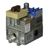
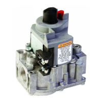
Related product manuals