Do you have a question about the Honeywell VK41 V Series and is the answer not in the manual?
Describes the function and application of the VK41/VK81 series gas controls in domestic heating equipment.
Details the different models, suffix letters, and connection types for the gas control series.
Covers ambient temperature, pressure regulation, outlet pressure, and operating pressure for the gas controls.
Details minimum regulation capacity, maximum air pressure, and offset range for gas flow control.
Details standard, external thread, and Mini-Venturi valve connection types and body lengths.
Specifies coil indication, supply voltage, and electrical connection details.
Describes permissible mounting orientations for the gas control unit.
Provides instructions for connecting the main gas supply, including internal thread and flange types.
Details 1/2" nut connections with flat sealing rings for 14mm and 15mm pipes.
Details 3/4" nut connections with olive or flat sealing rings for 15mm and 18mm pipes.
Outlines the 3/4" nut connection with O-ring for 15mm pipes.
Provides instructions for connecting the pilot gas tubing to the outlet side.
Details wiring, fusing, spark gap, and supply voltage polarity for electrical hookup.
Explains how to check and troubleshoot flame current issues for proper operation.
Describes how to use the pressure taps for testing and adjustment.
Details the procedure for adjusting the CO2 output at low and high burner settings.
Outlines steps for checking connections and overall cycle function after adjustments.
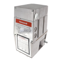
The Honeywell VK41..V(B)/VK81..V(B) series gas controls are designed for domestic appliances with premix burners and automatic ignition, offering a comprehensive solution for safe and efficient gas flow management. These controls integrate a 1:1 gas/air regulator, combining valve and ignition system functions into a single unit.
The primary function of these gas controls is to safely regulate gas flow to the main burner of domestic central heating equipment, warm air furnaces, back boilers, and water heaters. They achieve this through a sophisticated system that includes two electric on/off operators: a first safety valve of class B and a second servo operator of class B or C, both compliant with EN 161 standards. The integrated pressure regulator meets class B requirements of EN 88, ensuring precise control over gas pressure.
For applications requiring automatic ignition, the VK41..V series gas controls are specifically designed to have an S4565 series ignition control directly attached to the valve. This combined system facilitates programmed safe light-up, continuous flame supervision, and accurate regulation of gas flow to the appliance's main burner. This integration streamlines the ignition process, making it reliable and safe.
The VK41..V/VK81..V models are versatile, capable of handling all three gas families: manufactured gas, natural gas, and LP gas. This broad compatibility makes them suitable for a wide range of installations. In contrast, the VK41..VB/VK81..VB models are designed exclusively for second family gas, catering to specific regional or application requirements.
These gas controls can also be used as standalone units in direct burner applications. In such cases, a specific plug with an integrated rectifier circuit (order number 45.900.441-) is required to ensure proper operation. When integrated into a system, they work in conjunction with fan control and a direct spark ignition (DSI) control, forming a complete and approved system in accordance with European standards.
The electrical components of the gas control are designed for safety and reliability. The 24 V and 220/240 V versions can be connected to any standard DBI control with a 24 Vac or 220/240 Vac output by using the rectifier plug. This ensures compatibility with common ignition systems and provides electrical protection with an IP 40 rating when the rectifier plug is used.
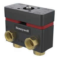
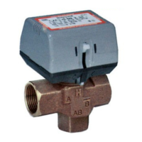
The VK41..V(B)/VK81..V(B) series offers flexible installation options, with various connection types to suit different piping configurations. These include standard valve connections, external thread valve connections, and Mini-Venturi valve connections, available with different inlet, end outlet, and side outlet options. Flanges are designed to meet EN 126 group 2 torsion and bending stress requirements, while external thread connections with nuts comply with ISO 228-1 and EN 126 group 1 standards.
The gas control can be mounted in any direction from 0 to 90° from the upright position, meaning the electric coils can be on top or at various angles, providing significant flexibility in appliance design and installation.
For main gas connections with internal threads, installers must ensure that no dirt enters the gas control during handling. A sound taper fitting or properly reamed pipe should be used, and thread compound should be applied moderately to the pipe or fitting only, leaving the two end threads bare. PTFE tape can be used as an alternative if permitted by local safety regulations. It is crucial not to overtighten pipes or fittings to prevent distortion and malfunction.
For flange connections, "O"-rings must be inserted into the groove of each flange, with a slight grease application if necessary to keep them in place. The gas control is then mounted between flanges using four screws.
Pilot gas connections, where applicable, are standardized at the end outlet with an M8 x 1 fitting for 4 mm outer diameter tubing. When connecting pilot gas, the end of the tubing should be squared off, burrs removed, and the compression fitting slipped over the tubing. The tubing is then inserted into the gas control housing until it bottoms, and the fitting is tightened about 1.5 turns beyond finger tight. Jointing compound should not be used for this connection.
Under normal circumstances, the VK41..V(B)/VK81..V(B) series gas controls require no maintenance or service. The device is designed to be a sealed unit, and disassembly is strongly discouraged. It contains no replaceable components, and any attempt to disassemble or repair it can damage the gas control. Screws on the valve that have been sealed must never be removed.
However, certain checks and adjustments are part of the installation and commissioning process. These must be performed by qualified persons following the appliance manufacturer's instructions or the provided procedure.
Gas Leak Test: After any work on the gas control or connections, a gas leak test is mandatory. All pipe connections upstream of the gas control should be painted with a rich soap and water solution; bubbles indicate a leak. If a leak is detected, the connection must be tightened. Once the main burner is in operation, all pipe joints, including adapters, and the gas control inlet and outlet should be painted with an approved leak detection fluid. If a leak persists, the part must be replaced. It is crucial to keep soap and water solutions away from electrical connections.
Pressure Tap: The gas control includes a pressure tap of 9 mm O.D. at both the inlet and outlet sides. To check pressure, the screw should be undone a half turn, a tube slipped over the nipple, and the screw retightened after the test.
Offset Adjustment: This adjustment is performed to set the CO2 % at the desired value at low output. It involves removing a cap screw to expose the offset adjustment screw, checking gas supply pressure, starting the fan and air flow, energizing both electric operators, and then adjusting the offset screw. Turning the screw clockwise increases CO2 %. After adjustment, the boiler should be operated on high output (for modulating applications), and the cap screw and pressure taps replaced and tightened.
Electrical Connections: All wiring must comply with local regulations and the appliance manufacturer's instructions. Lead wires must withstand 105 °C ambient temperatures and be proven against moisture. The wiring between the ignition control and the spark sensing probe must have good quality insulation. The ignition control has an integral non-replaceable fuse to prevent unsafe conditions from high current.
Flame Current Check: To ensure proper flame detection, the minimum flame current should be in accordance with the specified value of the ignition control. A DC micro-Ampèremeter can be connected between the flame sensing wire and rod to check the current. If insufficient, the flame sensing rod should be checked to ensure it is fully enveloped by the flame and that the burner is reliably grounded to the ignition control. A warning is issued to short the µA meter during ignition in single rod applications to prevent damage.
These comprehensive features ensure the safe, efficient, and reliable operation of domestic heating appliances.
| Gas Type | Natural Gas, Propane |
|---|---|
| Voltage | 24 VDC |
| Output Type | Relay |
| Number of Outputs | 4 |
| Communication Protocol | Modbus RTU |
| Application | Commercial and Industrial Gas Burner Control |