Do you have a question about the Honeywell VB6 Series and is the answer not in the manual?
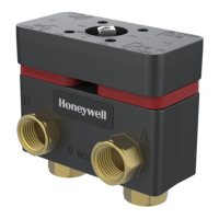
The Honeywell VB6 Series 6-Way Control Ball Valves and Actuators are designed for regulating hot and chilled water, including glycol solutions up to 60%, in heating, ventilating, and air conditioning (HVAC) systems. These valves are specifically intended for use in closed-loop applications with a media temperature range of 0°F to +212°F (18°C to 100°C) and static pressures up to 600 psi. Each valve ships with a direct-coupled MN7510A2001 actuator, factory-installed for modulating control, and is designed to be used exclusively with this actuator.
The VB6 series valves utilize a patented seat design that reduces the required operating torque, which is nominally 88 lb-in. They feature a true equal percentage flow characteristic, achieved through precision-machined metal discs positioned in front of the ball. This design allows for accurate and consistent flow regulation. The 6-way valve has two CV calculations, one for Sequence 1 and one for Sequence 2, which typically feature different flow rates.
The actuator can operate in several run modes, selected via a function selection switch: Modulating, Floating/2-position, and Service/Off. In Modulating Run mode, the actuator responds to control signals (2-10 Vdc, 0-10 Vdc, 10-0 Vdc, or 10-2 Vdc) to position the valve. Upon power application, the shaft adapter will first run completely counterclockwise, then completely clockwise, before operating according to the control signals. The valve's zero (closed) position for both Sequence 1 and Sequence 2 is achieved at a 45-degree actuator rotation, corresponding to specific control signal outputs (e.g., 5 Vdc for 0-10 Vdc input).
In Floating/2-position mode, the MN7510A2001 actuator is not recommended for 6-way valves because both Sequence 1 and Sequence 2 are closed at the actuator mid-stroke (45-degree rotation). Achieving precise mid-stroke positioning is difficult in floating mode and impossible for 2-position control. However, if the goal is simple seasonal changeover service with three distinct positions (fully clockwise for Sequence 2 open, fully counterclockwise for Sequence 1 open, and exactly mid-stroke for both closed), this can be achieved using the modulating modes. If only two positions (Sequence 1 open and Sequence 2 open) are desired without a precise mid-stroke closed position, the floating mode can be used for 3-wire 2-position control.
The actuator also provides a feedback signal proportional to the actual position of the shaft adapter, which can be wired via terminal 5. If power is removed, the shaft adapter remains in its last position. The actuator can be overridden to the 50% position (closing both Sequence 1 and Sequence 2) by applying a 24V signal to terminal 4, which causes the actuator to ignore the control signal at terminal 3.
Proper valve sizing is crucial for correct system operation. Undersized valves may lack sufficient capacity at maximum load, while oversized valves can lead to insufficient authority in modulating applications, causing excessive cycling and potential damage to the seat and ball due to restricted opening.
For installation, the valve should be held with a pipe wrench by its hexagonal fitting ONLY, avoiding the valve body itself to prevent damage. The actuator stem must be positioned horizontally to upright vertically, never below horizontal, to prevent condensate from flowing into the gearbox or actuator. The actuator is assembled onto the valve body by first ensuring the gearbox is in the zero position, then sliding the actuator into the actuator pedestal. The stem adapter is inserted into the actuator output hub, ensuring the notch on the stem adapter points correctly for zero position alignment. The brass sleeve is then slid over the stem adapter, and the actuator assembly is placed on the valve body. A screw and washer are used to firmly assemble the actuator with the valve body. A handle can be attached to the linkage stem adapter knob for manual operation.
To ensure trouble-free operation and maintain the valve warranty, good installation practices are essential. This includes initial system flushing and chemical water treatment. Lines upstream of the valve must be cleaned of particles larger than 1/16 inch diameter (e.g., welding slag, pipe scale, sand). A 50-micron (or finer) system side stream filter is recommended, with all filters removed before flushing. The presence of excessive iron oxide (red rust) in the system voids the valve warranty.
It is critical not to use boiler additives, solder flux, or wetted materials that are petroleum-based or contain mineral oil, hydrocarbons, or ethylene glycol acetate. Acceptable compounds, with a minimum 40% water dilution, include diethylene glycol, ethylene glycol, and propylene glycol (antifreeze solutions). When installing in existing buildings, it's important to verify that the fluid in the piping meets these criteria.
For manual adjustments, power must be removed or the function selection switch set to the "Service/Off" position to prevent equipment damage or electrical shock. In "Service/Off" mode, all rotary movement is canceled, and control signals are ignored, allowing manual operation. The Declutch button can be pressed and held to disengage the gearbox, permitting the handle to be manually rotated to any position.
To avoid water condensation dripping from the 6-way valve, insulation should be applied around the pipe connections and the structural box, but not over the gearbox. When clearing threads on the valve and piping, any debris should be removed. Honeywell recommends Permabond A1044 or an equivalent thread or pipe sealant. If using Teflon tape, 4-6 rounds applied tightly in a clockwise rotation are recommended, ensuring no strands are left in the valve or piping. Valves must be installed to avoid unnecessary pull or twist on the valve housing. A bracket should be used for non-flexible pipes to keep them firm and parallel. Only original Honeywell grommets should be used to guarantee an IP54 rating.
| Model | VB6 Series |
|---|---|
| Display | LCD |
| Connection Type | Screw Terminals |
| Body Material | Plastic |
| Type | Controller |
| Communication Protocols | Modbus RTU |
| Application | Building automation, HVAC control |
| Weight | Varies by model |