VB6 SERIES 6-WAY CONTROL BALL VALVES AND ACTUATORS - INSTALLATION INSTRUCTIONS
31-00380M-02 Printed in USA 4
Mechanical Installation for
Actuator
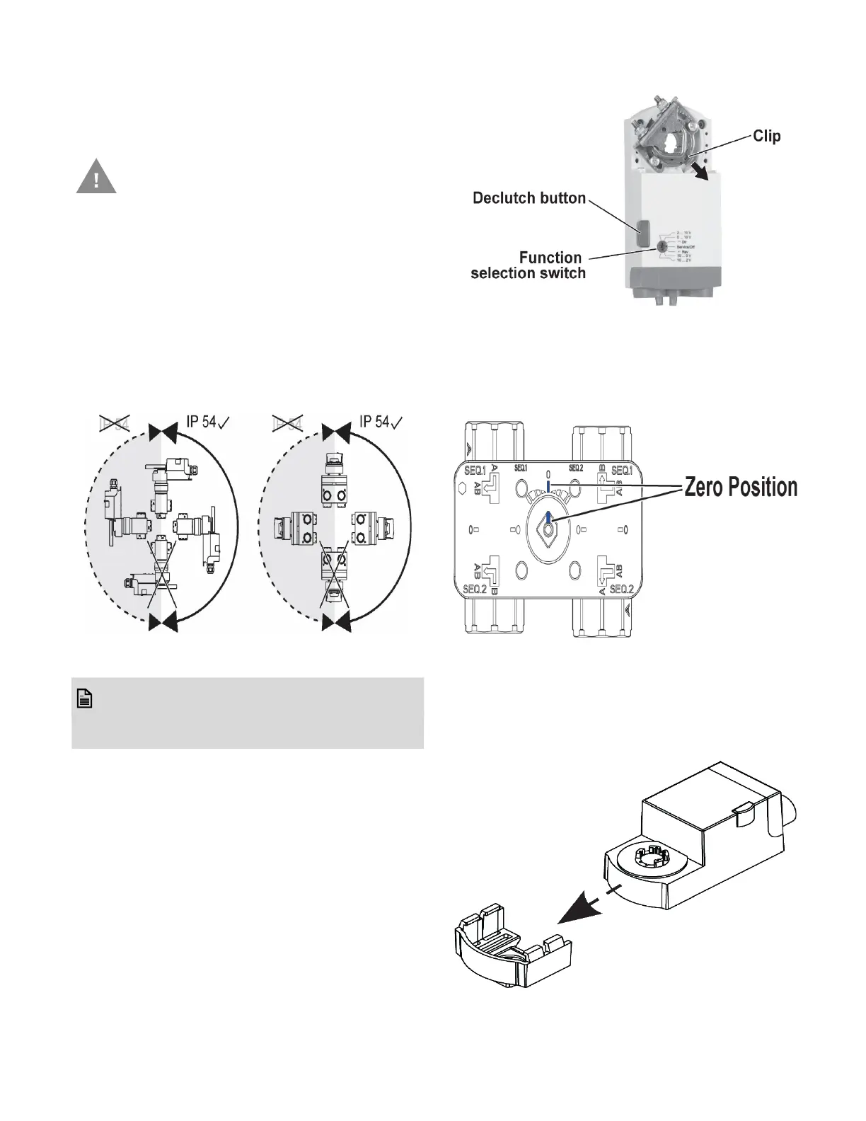
Mounting Position
1. Choose a mounting position permitting easy
access to cables and controls.
2. Make sure that the actuator stem is in
horizontal to upright vertical position, but
never in below horizontal position.
Condensate from Valve body may flow into
the Gear box or actuator, causing damage.
Figure 3. Actuator mounting
NOTE:NOTE:
Further, in order to guarantee IP54, only
original Honeywell grommets may be used.
Preparing Actuator for mounting
1. Use a suitable plier to hold the clip of the Uni-
versal shaft adapter.
2. Pull out the Clip as shown in below figure to
remove Universal shaft adapter. Now, the
actuator is ready to assemble on 6-way
control ball valve.
Assembling the actuator on Valve body
1. Make sure that the Gear box is in zero posi-
tion as shown in below figure. Use the appro-
priate wrench to adjust (if necessary).
Figure 4. Zero position of Gear box on Valve body
2. Slide the actuator into Actuator pedestal as
shown in below figure. Do not use additional
tools or pressure as the Actuator pedestal is
designed to press fit with the MN7510A2001
actuator.
Figure 5. Assembly of Actuator pedestal
Caution: To avoid personal injury
(electrical shock) and to prevent
equipment damage, before
installation, you must remove power.
 Loading...