3 EN1R-9134 0503R20NE
Table 1. Standard valve connection
Table 2. External thread valve connection
Table 3. Mini-Venturi valve connection
Capacity (∆
∆∆
∆p = 5 mbar, 1013 mbar and 15 °C)
VK4110V/VK8110V: 3.2 m
3
/
h
air
VK4115V/VK8115V: 3.4 m
3
/
h
air
VK4125V/VK8125V: 2.2 m
3
/
h
air
VK4115VB/VK8115VB: 4.4 m
3
/
h
air
NOTE: Versions with side outlet connection only have a
0.2 m
3
/
h
air lower capacity.
Versions with external thread connection have a
0.3 m
3
/
h
air lower capacity.
Capacity curves are available on request.
Valve classification
Timing
Closing time: ≤ 1 s
Opening time: see table
Mounting holes
Two mounting holes at the bottom for thread forming screws.
The four holes at inlet and outlet for mounting a flange on the
gas control are provided with M4 thread with min. 6 mm full
thread.
In case of side outlet the three holes for mounting the flange
are provided with M5 thread with a minimum of 6 mm full
thread.
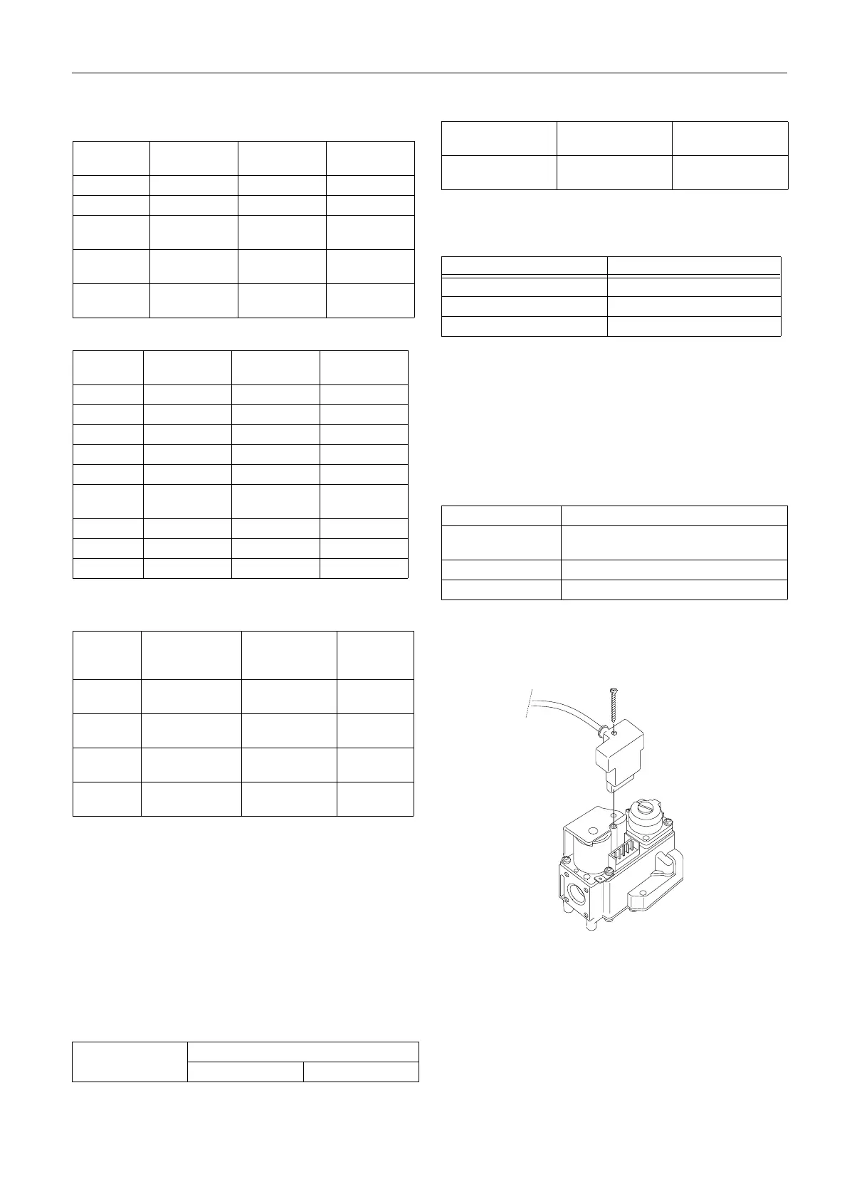
Electrical data
Electrical connection
Molex 1.1 square pin header
The 24 V and 220/240 V versions gas controls can be
connected to any standard DBI control with a 24 Vac, or
220/240 Vac output by using a rectifier plug 45.900.441-
Fig. 2. Mounting of rectifier plug
IMPORTANT
Warranty claims are not accepted if not the
specified plug/rectifier circuit is used.
Electical protection of gas control with rectifier plug
IP 40
Inlet End outlet Side outlet Body length
(mm)
Flanged Flanged -- 105
Flanged -- Flanged 105
Internal
3
/
8
”
ISO 7-1
-- Flanged 115
Internal
1
/
2
”
ISO 7-1
-- Flanged 115
Internal
1
/
2
”
ISO 7-1
Internal
1
/
2
”
ISO 7-1
-- 115
Inlet End outlet Side outlet Body length
(mm)
G
1
/
2
” G
1
/
2
” -- 135
G
1
/
2
” Flanged -- 120
G
3
/
4
” G
3
/
4
” -- 135
G
3
/
4
” Flanged -- 120
G
3
/
4
” -- Flanged 120
G
3
/
4
” Internal 1
1
/
2
”
ISO 7-1
-- 120
G
1
/
2
” -- Flanged 120
Flanged G
1
/
2
” -- 120
Flanged G
3
/
4
” -- 120
Inlet End outlet Side outlet Body
length
(mm)
Flanged Quick connect
mini-venturi
- 120
Flanged - Quick connect
mini-venturi
105
G
3
/
4
” Quick connect
mini-venturi
- 135
G
3
/
4
” - Quick connect
mini-venturi
120
Type Class
1
st
valve 2
nd
valve
VK4110/VK4115
VK8110/VK8115
Class B Class C
VK4120/VK4125
VK8120/VK8125
Class B Class B
Model Time till P
o
>= 100 P
a
VK4115V/VK8115V < 1 s
VK4115VB/VK8115VB < 1.5 s
VK4125V/VK8125V < 1.5 s
Coil indication Supply voltage
220/240 Vrac 220 V, 50/60 Hz using rectifier
240 V, 50/60 Hz using rectifier
110 Vrac 110 V, 50/60 Hz using rectifier
24 Vrac 24 V, 50/60 Hz using rectifier

 Loading...