INSTALL CONTROL
1. This control can be mounted 0-90 degrees, in any
direction, from the upright position of the gas control knob,
including vertically.
2. Mount the control so gas inlet is on the end with
projecting wrench boss. Refer to Figs. 3 and 4.
CAUTION
Never apply a jumper across (or short) valve coil
terminals. This may burn out thermostat heat anticipa-
tor.
IMPORTANT
These gas controls are shipped with protective seals
over inlet and outlet tappings. Do not remove seals
until ready to connect piping.
Follow the appliance manufacturer’s instructions if avail-
able; otherwise, use the instructions provided below as a
guide.
CHOOSE LOCATION
Do not locate the combination gas control where it may
be affected by steam cleaning, high humidity or dripping
water, corrosive chemicals, dust or grease accumulation,
or excessive heat. To ensure proper operation, follow these
guidelines:
• Locate in a well ventilated area.
• Mount high enough above the cabinet bottom to
avoid exposure to flooding or splashing water.
• Ensure that the ambient temperature does not ex-
ceed the ambient temperature ratings for each com-
ponent.
• Cover if appliance is cleaned with water, steam, or
chemicals or to avoid dust and grease accumulation.
• Avoid locating where exposure to corrosive chemical
fumes or dripping water is likely.
Mount the combination gas control in the appliance
vestibule on the gas manifold. If this is a replacement
application, mount the gas control in the same location as
the old control. Make sure the total control circuit wire length
does not exceed 30 ft [9.2 m] or 2-wire, 18 gauge cable or
50 ft [15.3 m] of 2-wire, 16 gauge cable.
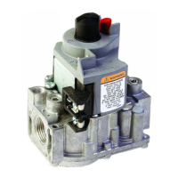
INLET AND OUTLET ADAPTERS
If adapters are needed, prepare control as follows:
1. Remove seal over control inlet or outlet.
2. Apply moderate amount of good quality pipe com-
pound to adapter, leaving two end threads bare. Refer to
Fig. 1. On LP installation, use compound resistant to LP
gas. Do NOT use Teflon tape.
3. Insert adapter in control and thread carefully until
tight.
Fig. 2—Sediment trap installation.
Fig. 3—Top view of standard capacity models.
Fig. 4—Top view of high capacity models.
INSTALL PIPING TO CONTROL
All piping must comply with local codes and ordinances
or with National Fuel Gas Code (ANSI Z223.1 NFPA No.
54), whichever applies. Tubing installation must comply
with approved standards and practices.
1. Use new, properly reamed pipe free from chips. If
tubing is used, make sure the ends are square, deburred
and clean. All tubing bends must be smooth and without
deformation.
2. Run pipe or tubing to control. If tubing is used, obtain
a tube-to-pipe coupling to connect tubing to the control.
3. Install sediment trap in the supply line to the gas
control. Refer to Fig. 2.
Fig. 1—Use moderate amount of pipe compound.
2
TWO IMPERFECT
THREADS
GAS CONTROL
THREAD PIPE THE AMOUNT
SHOWN IN TABLE FOR
INSERTION INTO GAS CONTROL
APPLY A MODERATE AMOUNT OF
PIPE COMPOUND TO PIPE ONLY
(LEAVE TWO END THREADS BARE).
M3075B
PIPE
GAS
CONTROL
GAS
CONTROL
HORIZONTAL
DROP
PIPED
GAS
SUPPLY
PIPED
GAS
SUPPLY
3 IN.
(76 MM)
MINIMUM
3 IN.
(76 MM)
MINIMUM
RISER
GAS
CONTROL
TUBING
GAS
SUPPLY
HORIZONTAL
DROP
3 IN.
(76 MM)
MINIMUM
RISER
M3077
2
1
2
2
1
2
ALL BENDS IN METALLIC TUBING SHOULD BE SMOOTH.
CAUTION: SHUT OFF THE MAIN GAS SUPPLY BEFORE REMOVING
END CAP TO PREVENT GAS FROM FILLING THE WORK AREA. TEST
FOR GAS LEAKAGE WHEN INSTALLATION IS COMPLETE.
 Loading...