EasyManua.ls Logo

Honeywell VS820 POWERPILE User Manual

Honeywell VS820 POWERPILE
4 pages
To Next Page IconTo Next Page
Page #1 background imageLoading...
Page #1 background image
APPLICATION
These gas controls combine a Lite-Rite manual
gas cock, safety shutoff Pilotstat assembly,
millivoltage automatic valve operator, and optional
gas pressure regulator. They require the use of a
750 mv Powerpile generator (thermopile). The
generator, heated by the pilot burner flame, pro-
vides the electrical energy to operate the combina-
tion gas control.
A millivoltage thermostat with suitable ac-
cessory controls completes the automatic control
system for the heating appliance.
Models equipped with the standard pressure
regulator are identified by the suffix letter “A“
WS820A.j Models without pressure regulator
carry the suffix letter “6” (VS820B). Suffix letter
“C” (VS82OC) identifies models having step
opening type regulators.
Pressure regulators and operator are standardiz-
ed and interchangeable on all models in the two
capacity ranges - 225 and 335 cubic feet per
hour.
PRESSURE REGULATOR ADJUSTMENT
LITE-RITE GAS COCK
(BENEATH COVER SCREW)
MANUAL KNOB \ \
*PILOT GAS OUTLET.
PRESSURE TAPPING
DIRECTLY BENEATH
PlLOTSTAi
POWER UNIT
\
PILOT FLOW ADJ. SCREW
(BENEATH COVER SCREW)
NOTE: 24 VOLT VALVE OPERATOR ILLUSTRATED
120 VOLT MODELS FEATURE TWO 36 INCH (914 mm) LEADS
WITH A TERMINAL COVER FOR CONDUIT CONNECTION.
MANUAL
GAS COCK
\
STANDARD
OUTLET
I,
INLET STRAIGHT
THROUGH
-4&.-W
A FLATS (VERTICAL) FOR l-7/8 INCH WRENCH
,a,,.
Fig. 2 - Piping pattern and dimensions (in inches) of
VS820.
SIZE PIPE TAPPINGS
225,000
I
II2
I
II2
335,000
I
314
I
314
PREPARE AND INSTALL PIPE
1. Use new, properly reamed pipe free from chips.
2. Do not thread pipe too far. Valve distortion or
malfunction may result from excess pipe within
control.
LENGTH OF STANDARD PIPE THREADS (inches)
4
Fig. 1 - Top view A model. Pressure regulator for “C”
model illustrated at right. (Blank cover plate
(Part No. 392782) is available to convert an
“A” model to a “B” model without pressure
regulator.)
3. Apply moderate amount of good quality dope to
pipe only, leaving two end threads bare. If LP gas in-
stallation, use compound resistant to action of li-
quified petroleum gases.
PROPER PIPING PRACTICE
2 IMPERFECT CONTROL USE MODERATE
THREAD PIPE RIGHT LENGTH
LEAVE 2 END
THREADS BARE
5-83
*TRADEMARK
PRINTED IN U.S.A.
Form Number 9!%10 0248-l
Residential Division
Question and Answer IconNeed help?

Do you have a question about the Honeywell VS820 POWERPILE and is the answer not in the manual?

Honeywell VS820 POWERPILE Specifications

General IconGeneral
BrandHoneywell
ModelVS820 POWERPILE
CategoryController
LanguageEnglish

Summary

Application Overview

VS820 Powerpile Combination Gas Controls

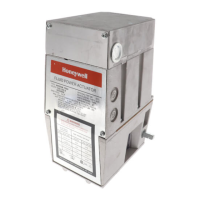
Description of the VS820 gas controls, including manual gas cock, safety shutoff, millivoltage operator, and optional regulator.

Model Identification and Capacity

Details on models A, B, C and their respective pipe tapping sizes for 225,000 and 335,000 BTU/hr capacities.

Pipe Preparation and Installation

Instructions on preparing and installing piping, including threading and dope application.

Installation Procedures

Installation Safety and Precautions

Essential cautions for installers, including turning off gas supply and not removing seals prematurely.

Connecting Pilot Gas Tubing

Steps for preparing and connecting pilot gas tubing, including tightening compression fittings.

Wiring Diagrams and Guidelines

Instructions on wiring millivoltage controls, emphasizing not connecting to line voltage.

Start-up and Adjustments

Gas Cock Settings

Explanation of the Lite-Rite gas cock knob settings: OFF, PILOT, and ON.

Pilot Lighting Procedure

Step-by-step guide to lighting the pilot burner and setting the thermostat.

Gas Leak Testing

Procedure for testing for gas leaks using soap and water solution.

Pilot Flame Adjustment

Instructions on adjusting the pilot flame to envelop 3/8 to 1/2 inch of the thermocouple tip.

Gas Input and Pressure Adjustments

Procedures for checking and adjusting gas input and manifold pressure for different models.

System Checkout

Final verification of control function through a complete cycle.

Troubleshooting and Maintenance

Pilot Goes Out When Knob Released

Troubleshooting steps for a pilot that extinguishes after the knob is released.

Component and Parts Replacement

Information on replacing valve operators, pressure regulators, and other components.

Electrical Data

Specifications for Pilotstat power unit and valve operator, including current and resistance.

Operating Instructions for Homeowner

Guidance for homeowners on using the gas controls, including lighting and shutdown.

Automatic Safety Shutoff

Explanation of the automatic safety shutoff function and what to do if it occurs.

Related product manuals