PILOT GOES OUT WHEN LITE-RITE KNOB IS
RELEASED
1. Check pilot flame adjustment. See page 3.
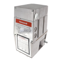
2. Check the Powerpile generator connection to
Pilotstat power unit (Fig. 1). This is an electrical con-
nection and must be clean and secure. Also check the
Powerpile generator connections to the valve operator.
3. If power unit still does not hold in, use the W720
Systems Tester to obtain the exact open and closed
circuit output voltages of the generator. Compare with
the Acceptable Range Charts in W720 manual or Gas
Controls Service Handbook. Next check resistance of
Pilotstat power unit.
If W720 or other meter is not available, first replace
generator. If this does not correct the condition
replace power unit (adjacent to gas cock knob - see
Fig. 1). Turn off gas supply to appliance (at service
cock or meter) and remove power unit with wrench.
Install and tighten new power unit. Turn on gas supply
and check for gas leakage.
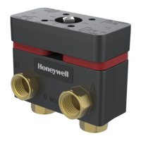
COMPONENT AND PARTS REPLACEMENT
The automatic valve operators and servo regulators
may be added in the field, or replaced in service
maintenance. (Model number is stamped on side of
component.) Complete instructions are furnished with
the component.
REPLACEMENT VALVE OPERATOR: VS824A.
REPLACEMENT SERVO PRESSURE REGULATOR:
V5306 standard and V5307 step opening type.
Either models are field addable to “B” models.
VS820 “A” or “C” models can be converted to
“B” models by removing the pressure regulator and
applying a blank plate and gasket, Pt. No. 392782.
REPLACEMENT PARTS:
Pilotstat power unit (750 mv) - 392395.
Compression fitting for pilot tubing connection-
386449.
Pilot gas filter - 391158.
OPERATING INSTRUCTIONS FOR THE
HOMEOWNER
‘MPORTANT
Follow the operating instructions provided by the
manufacturer of your heating appliance. The infor-
mation below will be of assistance in a typical con-
trol application, but the specific controls used and
the procedures outlined by the manufacturer of
your appliance may differ, requiring special
instructions.
LITE-RITE KNOB SETTINGS
Refer to GAS COCK SETTINGS, page 2.
TO LIGHT PILOT AND TURN ON MAIN BURNER
Follow PILOT LIGHTING PROCEDURE, page 3.
TO SHUT OFF
1. For TEMPORARY situations: Main burner can be
shut off by turning clockwise m from ON to
PILOT. Pilot will remain lit - ready for return to nor-
mal service without relighting. (This is the recom-
mended summer shutdown position.)
2. For COMPLETE SHUTDOWN: Slightly depress
Lite-Rite knob when at PILOT position and turn
clockwise m to OFF Both pilot and main burner
now are shut off.
AUTOMATIC SAFETY SHUTOFF
The automatic safety shutoff valve blocks gas flow
to the main burner and pilot burner if the pilot flame
goes out or becomes too small for adequate ignition.
If safety shutoff occurs, check pilot flame after
relighting and adjust if necessary. See ADJUST
PILOT FLAME, page 3. If shutoff reoccurs, contact
your local dealer or gas utility to correct condition
causing shutdown.
ELECTRICAL DATA:
Pilotstat Power Unit - Hold-in 15 ma maximum;
dropout 10.5 to 4.5 ma; resistance 11 ohms.
Valve Operator - Pull-in 65 ma maximum; coil
resistance 2 ohms.
This material is proprietary to Honeywell Limited and shall not be reproduced, copied or used in any manner without prior written consent of
Honeywell Limited.
HONEYWELL l 740 Ellesmere Road l Scarborough l Ontario MlP 2V9
 Loading...