WIRING
Follow wiring instructions furnished by appliance manu-
facturer, if available, or use general instructions provided
below. Where instructions differ, follow appliance
manufacturer’s instructions.
All wiring must comply with applicable electrical codes
and ordinances or with the National Electrical Code
(ANS1/
NFPA 70), whichever applies.
Disconnect power supply before making wiring connec-
tions to prevent electrical shock or equipment damage.
Wiring 24V Models
NOTE: The
V800
and V801 have a blue terminal block.
Terminals and markings are identical.
1. Make sure the power supply rating on each control
matches the available supply. Install transformer, low
voltage thermostat, and other controls as required.
2. Connect control circuit to operatorterminals. Refer to
Fig. 9 for typical 24V wiring diagram.
3. Adjust thermostat heat anticipator to 0.2A rating
stamped on valve operator.
,,,R:–~q_co.pLE
24 VOLT
HIGH LIMIT
THERMOSTAT
~.---
_-7
, CAUTION ,
CONTROLLER
A’
Iwl
I
-SEE 2
I
l~-i-l-
&
TRANSFORMER
,!+
—
,.
f!!!!
POWER SUPPLY PROVIDE DISCONNECT MEANS AND OVERLOAD PRO
TECTION
AS
REQUIRED.
~
NE”ER,”MPER
THESE
TERMINALS THIS
51+ORTSC3UT
“ALVE
COIL
AND
M4Y
BURN OUT HEAT ANTICIPATOR IN THERMOSTAT
~
ORDER
ECD
LIMIT
4ND
LE.4CIWIRES
SEPARATELY
2352.
FIG. 9—TYPICAL WIRING HOOKUP FOR 24V SYS-
TEMS.
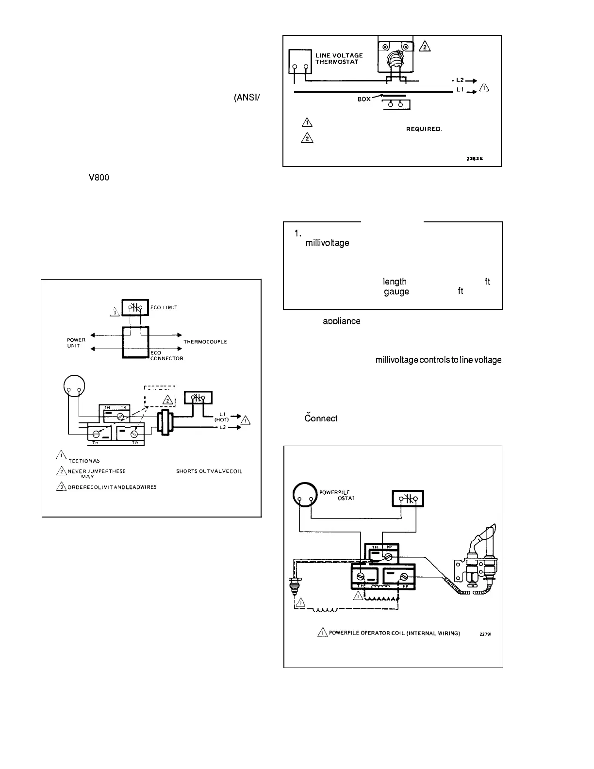
Wiring 110V, 120V, 220/240V Models
1. Make sure power supply rating on each control
matches available supply. Install line voltage thermostat
(or controller) and other controls as required. Refer to Fig.
10 for typical wiring diagram.
2. Use junction box, as shown, when connecting control
circuit to gas control operator. Make conduit connection to
operator as follows:
a. Slip conduit fittings over integral leadwires and
screw securely into hole in operator cover.
b. Cut flexible conduit to appropriate length. Slip
conduit over leadwires and attach to fittings.
c. Route and connect both flexible conduits to junc-
tion box. Connect integral wires to control circuit. Do
not splice except within a junction box.
LINE VOLTAGE
OPERATOR
OR CONTROLLER
L2+
.
I
I
1
Ll+~
1
JUNCTION
BOX-
,
,
db]
LIMIT
(HOT)
CONTROLLER
POWER SUPPLY. PROVIOE DISCONNECT MEANS ANO
OVERLOAD PROTECTION AS REQUIREO.
LINE VOLTAGE ENCLOSURE NOT PART OF GAS CON-
TROL. LINE VOLTAGE GAS CONTROLS MUST BE USED
IN AN OEM APPROVED ENCLOSURE.
2353E
FIG. 1O—TYPICAL WIRING HOOKUP FOR 120V SYS-
TEM.
Wiring Powerpile Models
IMPORTANT
1.
2.
Since the entire control system is powered by the
millivoltage
generated by the Powerpile genera-
tor, clean and scrape all wires before connecting.
Solder and tape all necessary splices using rosin
flux to prevent corrosion.
Control circuit cable
Ienath
must not exceed 30
ft
[9 mm] of 2-wire, 18 ga~ge cable, or 50
ft
[15 m]
of 2-wire, 16 gauge cable.
Follow
aooliance
manufacturer’s wirina instructions. if
available, or’ use general instructions p-rovided below.
Where instructions differ, follow appliance manufacturer
instructions.
Never connect these
millivoltagecontrolsto
Iinevoltage
or to a transformer.
To prevent electrical shock or equipment damage, dis-
connect power supply before making wiring connections.
1. After Powerpile generator is installed in pilot burner,
route aenerator lead to aas control.
2. ~onnect lead tog& control terminals labeled PP.
3. Connect thermostat leads as shown in Fig. 11 or 12.
$?
PowERPILE
THERM
OSTA1
w
HIGH LIMIT
CONTROLLER
l.++
—
,AAAA,—————_——
J
POWER UNIT CONTROL
~
POWERPILEOPERATOR
CO,
L(INTERNALW,RING)
22791
,F-
FIG. 11—TYPICAL WIRING CONNECTIONS FOR GAS
CONTROL WITH THREE-TERMINAL OPERATOR.
8
 Loading...


