,.
.,
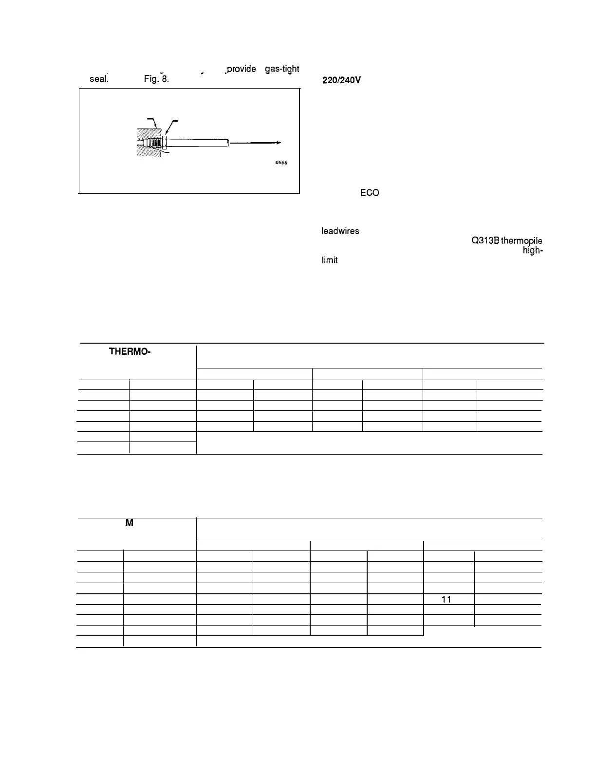
NOTE: When replacing a control, cut off old compression
fitting and replace with new compression fitting pro-
vided on new combination gas control. Never use old
compression fitting as it mav not
cwovide
a
aas-tiaht
.
.
.-
seal~
Refer to
Fig.-8.
GAS CONTROL
(INLET
END)
BODY
TIGHTEN NUT ONE TURN
BEYOND FINGER TIGHT
TO PILOT BURNER
FITTING BREAKS OFF
AND CLINCHES TUBING
AS NUT IS TIGHTENED
S988
FIG. 8-ALWAYS USE NEW COMPRESSION FITTING.
4. Push tubing into pilot gas tapping on outlet end of
the control until it bottoms. While holding tubing all the
way in, slide fitting into place and engage threads. Turn
until finger tight. Then tighten one more turn with wrench.
Do not overtighten.
5. Connect other end of tubing to pilot burner accord-
ing to pilot burner manufacturer’s instructions.
CONNECT THERMOCOUPLE (24V, 10OV, 120V, and
220/240V
models)
The thermocouple connection to the power unit or
ECO connector (Figs. 6 and 7) is an electrical connection
and must be clean and dry. Never use pipe compound.
Tighten only 1/4 turn beyond finger tight to give good
electrical continuity.
CONNECT ECO (Standard capacity 24V, 10OV, 120V,
and 220/240 models)
If the
ECO
is provided, the leadwires must be
equipped with insulated 1/4 in. female quick-connect ter-
minals. Leadwire lengths must not exceed the lengths
shown in Tables 5 and 6. Connect the high-limit or ECO
Ieadwires
to the two terminals on the ECO
If ECO is not provided, connect a
Q313B
thermopile
generator in place of the thermocouple to act as the
high-
Iimit
for the system.
TABLE 5—MAXIMUM LENGTH OF SUPPLEMENTARY LIMIT LEADWIRES
WHEN USING Q340A THERMOCOUPLE.
THERMO-
1
COUPLE
MAXIMUM LEADWIRE LENGTH X 2 (wires)
LENGTH
AWG NO. 14
AWG NO. 16
AWG NO. 18
in.
m
in.
m
in.
m
18
in.
m
0.5
35
0.9
22
0.6
13
24
0.3
0.6
29
0.7
18
0.5
11
30
0.3
0.8
23
0.6
15
0.4
9
36
0.2
0.9
17
0.4
11
0.3
6
48
0.2
1.2
DO NOT USE.
72
1.8
TABLE 6—MAXIMUM LENGTH OF SUPPLEMENTARY LIMIT LEADWIRES
WHEN USING Q309A THERMOCOUPLE.
COUPLE
MAXIMUM LEADWIRE LENGTH X 2 (wires)
LENGTH
AWG NO. 14
AWG NO. 16
AWG NO. 18
in.
m
in.
m
in.
m
12
in.
m
0.3
47
1.2
30
0.8
18
18
0.5
0.5
41
1.0
26
0.7
16
24
0.4
0.6
35
0.9
22
0.6
14
30
0.4
0.8
29
0.8
18
0.5
11
36
0.3
0.9
23
0.6
15
0.4
9
40
1.0
0.2
19
0.5
12
0.3
7
48
1.2
0.2
11
0.3
7 0.2
60
1.5
DO NOT USE.
‘4
7
60-2019-7
 Loading...


