INSTALL PIPING TO CONTROL
All piping must comply with local codes and ordi-
nances or with National Fuel Gas Code (ANSI Z223.1
NFPA No. 54), whichever applies. Tubing installation
must comply with approved standards and practices.
1. Use new, properly reamed pipe free from chips. If
tubing is used, make sure ends are square, deburred,
and clean. All tubing bends must be smooth and without
deformation.
2. Run pipe or tubing to the control. If tubing is used,
obtain a tube-to-pipe coupling to connect tubing to the
control.
3. Install sediment trap in gas supply line. Refer to
4. Apply a moderate amount of good quality pipe com-
pound (DO NOT use Teflon tape) to pipe only, leaving
two end threads bare. On LP installations, use compound
resistant to LP gas. Refer to Fig. 5.
,,
.-
2 IMPERFECT CONTROL
USE MO OERATE AMOUNT OF DOPE
I
THREAD PIPE RIGHT LENGTH
LEAVE 2 ENO
THREAOS
BAREJ
313E
I
FIG. 5—USE MODERATE AMOUNT OF PIPE COM-
POUND.
Fig. 4.
5. Remove seals over control inlet and outlet, if neces-
sary.
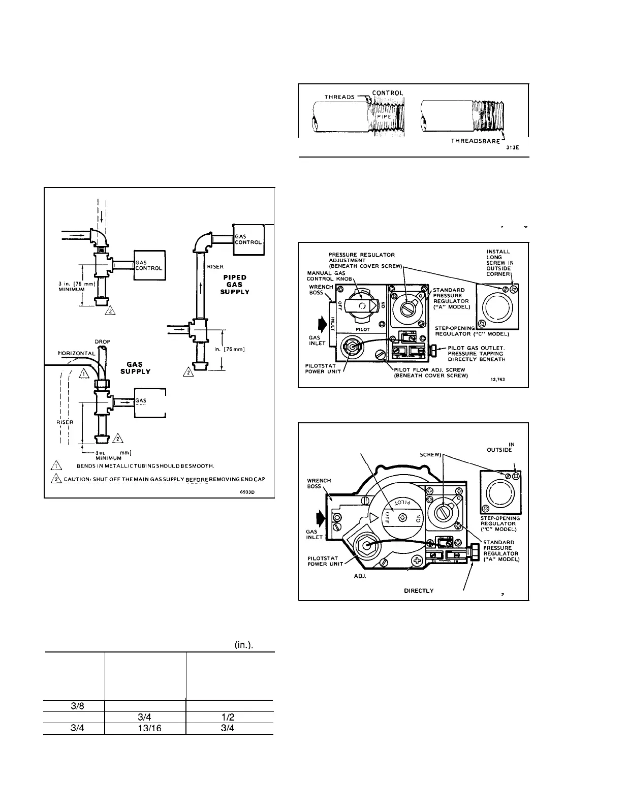
6. Connect pipe to control inlet and outlet. To tighten
inlet and outlet connections, use wrench on projecting
DROP
II
PIPED
II
GAS
Ill
SUPPLY
HORIZONTAL
I
h
*
;1
-L
—-l
,m
.-
wrench boss. Refer to Figs. 6 and 7.
#-
m
H(
—
/
Y1
//
GAS
‘u
3 1..’[76
mm]
MINIMUM
~-d
-II
TUBING
w,
----
!._
SUPPLY
E
R
,
_,
GAS
CONTROL
A
FIG. 6—TOP VIEW OF STANDARD CAPACITY GAS
CONTROL.
r’
1
/
PRESSURE
INSTALL
REGULATOR
LONG
ADJUSTMENT
SCREW
IN
(BENEATH COVER
OUTSIOE
‘CREW)W
CORNER
\
MANUAL GAS
CONTROL KNOB
/
‘3
,.. [76
mml
~
ALL
BENDS!:::flLLIC
TUBING
SHO”LD
BE
SMOOTH.
~CAUTION:*HUTOFFTHE
MAIN
GAS
SUPPLY
BEFORE
REh+CIVING
END
CAP
TO PREVENT GAS FROM FILLING THE WORK AREA. TEST FOR GAS LEAK-
AGE WHEN INSTALLATION IS COMPLETE.
6933D
FIG. 4—sEDIMENT TRAP INSTALLATION.
‘.
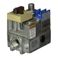
INSTALL CONTROL
1. This control can be mounted 0-90 degrees, in any
direction, from the upright position of the gas control
knob, including vertically.
2. Mount the control so gas flow is in direction of arrow
on bottom of control.
3. Thread pipe the amount shown in Table 6 for inser-
tion into control. DO NOT THREAD PIPE TOO FAR.
Valve distortion or malfunction may result if pipe is in-
serted too deeply.
PILOT FLOW
ADJ,
SCREW
(BENEATH COVER SCREW)
/
PILOT GAS OUTLET,
PRESSURE TAPPING
01
RECTLY BENEATH
1
,
>
,..
FIG. 7—TOP VIEW OF HIGH CAPACITY MODEL.
CONNECT PILOT GAS TUBING
1. Cut tubing to desired length and bend as necessary
for routing to pilot burner. Do not make sharp bends or
deform tubing. Do not bend tubing at control after com-
pression nut has been tightened, as this may result in gas
leakage at connection.
2. Square off and remove burrs from end of tubing.
3. Unscrew brass compression fitting from pilot gas
outlet (Figs. 6 and 7). Slip fitting over tubing and slide out
of way.
TABLE 6—NPT PIPE THREAD LENGTH
(in.).
MAXIMUM DEPTH
PIPE CAN BE
PIPE SIZE
THREAD PIPE INSERTED INTO
PIPE SIZE
THIS AMOUNT
CONTROL
3/8
9/1 6
31a
112
314
112
314
13116
314
6
 Loading...


