7 60-2102—7
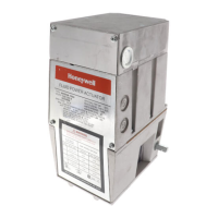
Fig. 8—Recommended arrangement for
normally closed operation.
V51E
INSTALLATION
5. Use the four large cap screws supplied with the link-
age assembly to secure the motor to the adapter plate.
6. Add the ball joint assembly and push rod as shown in
Fig. 10.
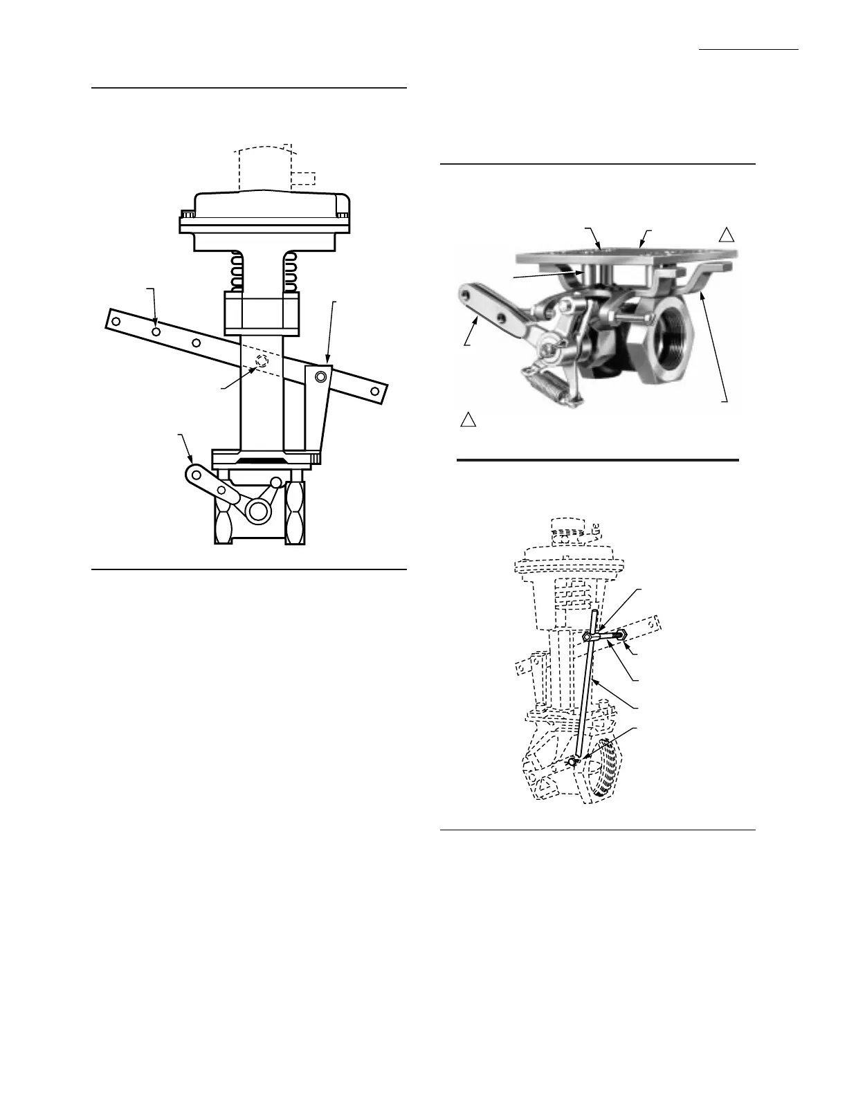
Fig. 9—Relationship of parts in V51E.
M9528
LOAD
TAKEOFF
CLEVIS
VALVE ACTUATING ARM
(VALVE CLOSED)
PIVOT
(THREADED
HOLE IN
LEVER)
1. Remove the four round-head machine screws and
washers holding the stop bracket to the valve hex at each end.
Do not remove the stop bracket
2. Position the adapter plate over the stop bracket so that
the adapter plate holes match the stop bracket holes.
3. Insert the flat head screws supplied with the linkage
assembly through plate, spacers, and stop bracket and into
each hex. Tighten securely. The spacers prevent contact of
adapter plate and stop bracket. See Fig. 9.
4. Mount the lever arm (13-3/4 in. [349.3 mm]) supplied
with the motor so the load takeoff holes will be at the same
end of the valve as the valve actuating arm.
NOTE: Both motor lever and valve arm could be installed
180 degrees from the positions shown in Figs. 7 and 8, if
more convenient. Use bushing hole at the clevis.
Fig. 10—Typical combination of V51E, Air-O-
Motor Pneumatic Actuator, and Q524 Linkage.
UPPER
BALL JOINT
1 NUT EACH
SIDE OF LEVER
BALL JOINT
ASSEMBLY
PUSH ROD
LOWER
BALL JOINT
M9583
FLAT HEAD SCREWS (4)
ADAPTER PLATE
SPACERS (4)
STOP
BRACKET
VALVE
ACTUATING
ARM
SUPPLIED WITH LINKAGE.1
M9536
1
 Loading...