EasyManua.ls Logo

Honeywell VAM User Manual

Honeywell VAM
8 pages
To Next Page IconTo Next Page
Page #1 background imageLoading...
Page #1 background image
VAM (VISTA Automation Module) - Installation & Setup Guide
Introduction
VISTA Automation Module (herein referred to as “VAM”) combines home automation and home security and is intended
for use with compatible VISTA
®
series control panels. VAM includes a built-in web server, Wi-Fi
®
capability, and Z-Wave
®
technology allowing VISTA installations to support Z-Wave devices.
The VISTA Automation Module also supports Remote Services for controlling Z-Wave devices and Scenes remotely from
an associated Total Connect™ account.
VAM is controlled using a web browser on a Wi-Fi enabled smart device such as a Tablet PC, laptop, Smartphone, etc.
DISPLAY NOTE: For optimum viewing of the screens and menus, the tablet’s font size setting may need to be adjusted.
Make Wiring Connections
Connect VAM to the control panel’s keypad data (ECP)
terminals using a standard 4-wire keypad connector harness.
Wire Connections to the Control Panel
Verify that VAM and other connected devices do not exceed the
control’s Aux Power output capability. If it does, use a
supplementary power supply as shown.
IMPORTANT: When VAM is powered from an auxiliary power
supply, always apply power to the control panel first
and then VAM.
Failure to observe this sequence results in improper operation of
VAM and may result in an ECP Error indication.
Supplementary Power Connections
Mount the VAM
VAM is for indoor use only and should be mounted near the
control panel or a keypad connected to the control panel for
ease of wiring.
VAM mounts to a wall surface by hanging on two screws. See
the diagram below.
Leave the screw heads 1/8” above the wall surface.
If necessary, drill a hole in the wall for the wire harness to
pass through.
Connect the wire harness to the VAM before mounting.
Refer to control panel’s installation instructions for ECP wire
limitations.
Insert an SD/SDHC Memory Card
An SD card must be installed to receive automatic software
upgrades. The SD card can be left in the VAM. See Software
Upgrades section.
Avoid touching the contacts on the card
4GB SD card supplied
Supports up to 16GB SD Card
Insert the memory card (SD/SDHC Card) as shown.
\
Question and Answer IconNeed help?

Do you have a question about the Honeywell VAM and is the answer not in the manual?

Honeywell VAM Specifications

General IconGeneral
Wi-FiYes
Ethernet LAN-
USB ports quantity0
Connectivity technologyWireless
Control typeButtons, Touch
Product colorBlack
Input voltage12 V
CompatibilityVISTA, Z-Wave devices, IP cameras
Mobile operating systems supportedAndroid, iOS
Weight and Dimensions IconWeight and Dimensions
Depth12.7 mm
Width209.6 mm
Height152.4 mm

Summary

Physical Installation and Setup

Make Wiring Connections

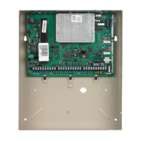
Connect VAM to control panel ECP terminals using 4-wire harness.

Mount the VAM

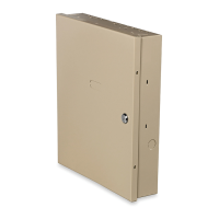
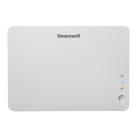
Mount VAM to wall surface using screws, ensuring proper clearance for wiring.

Insert an SD/SDHC Memory Card

Install SD card for automatic software upgrades and data storage.

VAM Device Overview and Specifications

Front Panel LEDs

Description of VAM's Power, Network, and Operation status LEDs.

Specifications

Physical and environmental specifications for the VAM module.

WiFi Network Setup

Set Up the WiFi Network

Steps to connect VAM to a smart device and home router via Wi-Fi.

Retrieve and Save VAM's Network IP Address

Steps to find and save the VAM's assigned IP address after connecting to the router.

Check Smart Device Connection

Verify smart device is connected to the correct router after VAM reboot.

Complete Setup and Bookmark URL

Finalize VAM connection and bookmark the access URL for future use.

Control Panel and VAM Integration

Program the Control Panel for use with VAM

Assigning an ECP address for VAM in the control panel.

VAM Configuration and Services

Program the VAM Device Address

Setting the VAM's device address within its own interface.

Set the Time & Date

Manually setting or retrieving time/date from the control panel.

Set Up Remote Services (Total Connect™)

Enabling remote access via Total Connect, requiring an AlarmNet Direct account.

Enabling Devices for Total Connect

Selecting which Z-Wave devices are controllable via Total Connect.

Z-Wave Device Management

Adding Z-Wave Devices

Instructions for enrolling Z-Wave devices like locks, thermostats, and cameras.

Removing All Z-Wave Devices

Procedure to factory default the Z-Wave controller and remove all devices.

Automation and Z-Wave Features

Automation & Creating Scenes

Defining triggers, conditions, and actions to automate devices.

Creating Rooms & Groups

Organizing Z-Wave devices into rooms or groups for scene definition.

Using VAM as a Secondary Controller

Configuring VAM to work with another primary Z-Wave controller.

Z-Wave Troubleshooting

Guidance on common issues when adding or managing Z-Wave devices.

Software and Access Management

Software Upgrades

Procedures for automatic and manual software updates for the VAM.

Set Up Remote Access (Account Setup)

Configuring user accounts for remote access to VAM menus.

Options

Installer-only settings for VAM modes (Normal/Demo).

Compatible Z-Wave Devices

List of known compatible Z-Wave devices for use with VAM.

Regulatory and Support Information

FCC and IC Statements

Compliance statements for Federal Communications Commission and Industry Canada.

RF Exposure Warning

Safety warning regarding minimum separation distance from persons.

Navigation & Menu Icons

Reference guide for icons used in the VAM Wi-Fi interface.

Documentation and Online Support

Information on where to find the latest documentation and support.

Related product manuals