W7100G DISCHARGE WATER TEMPERATURE CONTROL
63-4046—1 4
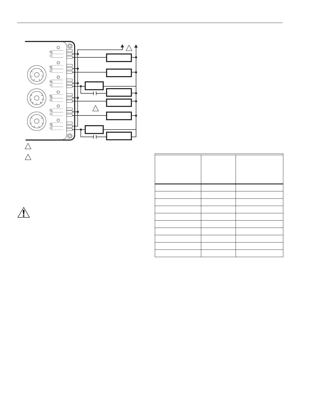
Fig. 3. Wiring W7100G using minimum on and minimum
off timer(s) on compressor stages.
Wiring
W7100G wiring and hookup diagram is shown in Fig. 4.
CAUTION
Erratic System Operation Hazard.
Failure to follow proper wiring practices can
introduce disruptive electrical interference (noise).
Keep wiring at least one foot away from large inductive
loads such as motors line starters, lighting ballasts,
and large power distribution panels.
Shielded cable is required in installations where these
guidelines cannot be met.
Ground shield only to grounded controller case.
Changing Number of Controlled Stages
A fixed resistor is installed across the number of stages input
(terminals 7 and 8). The resistor value tells the W7100G how
many stages of cooling are to be controlled. This affects the
control behavior and determines how many stages the
W7100G will turn on and off.
A resistor is initially installed by the factory (600ohm) on
terminals 7 and 8 (see Table 2). This corresponds to the value
for controlling a 6-stage cooling system. If the system being
installed has more or fewer stages of cooling, this resistor
must be changed to the value shown in Table 2. The new
value represents the actual number of cooling stages
operating under the control of the W7100G. This includes
any stages on a W7101A sequencer connected to the
W7100G control.
Connecting Additional Stages
Control of up to 4 additional stages of ON/OFF cooling can
be added by using a W7101A Satellite Sequencer to the
W7100G system as shown in Fig. 4.
The fixed resistor value across the W7100G terminals 7 and 8
(Table 2) must agree with the total number of cooling stages
controlled by the W7100G and W7101A satellite. See W7101
specification sheet, Form 63-2119, for additional details.
Table 2. Input Resistance for Number
of Controlled Stages.
a
Use 1/8W resistors.
b
4074EFV Bag Assembly available separately.
M17916
POWER SUPPLY. PROVIDE DISCONNECT MEANS
AND OVERLOAD PROTECTION AS REQUIRED.
TIMER MUST BE MINIMUM OFF TYPE TIMER.
4 MINUTES MINIMUM ON AND OFF IS RECOMMENDED.
60
50
40
20
30
10
SETPOINT F
15
10
5
10
8
64
2
CONTROL BAND
20
0
B
C
A
B
C
A
B
C
A
B
C
A
B
C
A
B
C
A
COOL 6
COOL 5
COOL 4
COOL 3
COOL 2
COOL 1
RESET F
1
W7100G
CUTOUT
UNLOADER
UNLOADER
COMPRESSOR
TIME
DELAY
TIME
DELAY
UNLOADER
UNLOADER
COMPRESSOR
1
2
2
F
TDR-2
TDR-2
TDR-1
POWER SUPPLY
TDR-1
Total Number of
Cooling Stages
Resistance
±1% Across
Terminals
7 and 8
a
(Ohms)
4074EFV Bag
Assembly Wire
Colors
b
1 (W7100 only) 100 Blue
2 (W7100 only) 200 Red
3 (W7100 only) 300 Yellow
4 (W7100 only) 400 Brown
5 (W7100 only) 500 Green
6 (W7100 only) 600 Shipped with Control
7 (W7100,W7101A) 700 Orange
8 (W7100,W7101A) 800 White
9 (W7100,W7101A) 900 Violet
10 (W7100,W7101A) 1000 Black
 Loading...