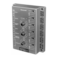
W7100G DISCHARGE WATER TEMPERATURE CONTROL
9 63-4046—1
SYSTEM CHECKOUT
To field test the system, follow the steps detailed in Table 4. In
order to complete this checkout, the following equipment is
required:
— 4074EDJ Test Plug and Resistor Bag Assembly.
— 4074EFV Resistor Bag Assembly.
— Digital VOM meter.
— 195770A Test Plug.
Table 4. W7100G System Checkout.
Step Action Verification
1 Disconnect power from W7100. Check for 0 Vac across W7100 TR and TR terminals.
2 Disconnect compressor and unloader line voltage power. Check for 0 Vac at compressor and unloader contactors or
relays.
3 Remove C7170A Sensor leads from W7100 and replace
with 4074EDJ Bag Assembly 3400 ohm resistor (blue
leads).
—
4 Remove from W7100 any jumper installed on the Fast
Response Terminals (9 and 10).
—
5 Remove from W7100 terminals 6 and 7 all wires. Place a
4074EDJ Bag Assembly 1780 ohm resistor (red leads).
—
6 Jumper W7100 terminals P and P1. —
7 Remove red plastic dust plug from W7100 bottom and install
195770A Test Plug in the revealed socket.
—
8 Set W7100 reset knob at 20°F (11K) —
9 Set W7100 setpoint at 10°F (-12°C) —
10 Connect 24 Vac power to the W7100 (TR and TR terminals) Check for 24 Vac across W7100 TR and TR terminals.
11 Wait 15 seconds. —
12 All W7100 stages should be energized All red LED should be on.
13 Adjust W7100 setpoint to 60°F (16°C). —
14 Wait 15 seconds. —
15 All W7100 stages should be off. All red LED should be off.
16 Remove 1780 ohm resistor from W7100 terminals 6 and 7. —
17 Jumper W7100 terminals 6 and 7. —
18 Adjust W7100 setpoint to 50°F (10°C) —
19 Wait 15 seconds. —
20 All W7100 stages should be energized. All red LED should be on.
21 Disconnect power from W7100. Check for 0 Vac across W7100 TR and TR terminals.
22 Reconnect all wiring as originally installed. —
23 Remove 195770A Test Plug and install red plastic dust
cover.
—
24 Reconnect W7100 power supply, close compressor
disconnects, and place W7100 setpoints where desired.
System is now operational.
 Loading...