EN I 8
FINAL INSTALLATION
Figure 5.5
Figure 5.8 Figure 5.9
Figure 5.4
Figure 5.7
Figure 5.6
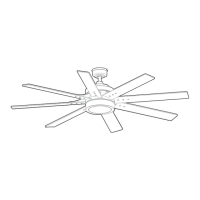
Blade Screw
Screw Cap
Blade Arm
Blade Arm
Motor Screw
Lens Cover
Light Kit
Wall
Bracket
Wall Bracket
Screw
Light Kit
Single-pin
Connector
Fitter Plate
Screw
Blade
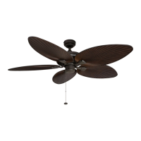
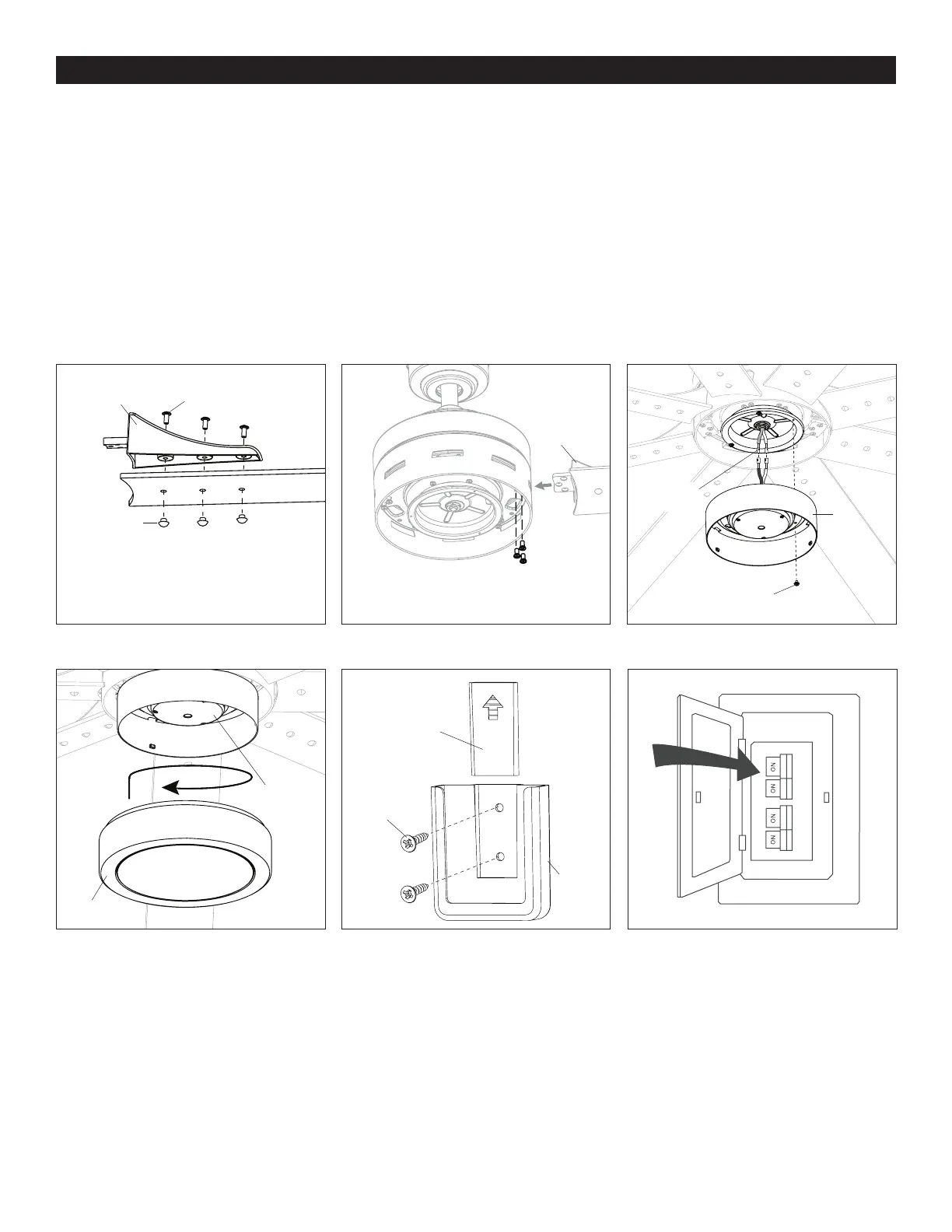
4. Partially insert three blade screws through the blade arm and the blade. Secure each blade screw with a blade screw cap, starting
with the one in the middle. Repeat this step for the remaining blades and blade arms (Figure 5.4).
5. Insert blade arm through slots in the side of the motor assembly. Align the holes of one blade arm with three motor screw holes
in underside of the motor assembly. Secure with three motor screws. Repeat this step for the remaining blade arms (Figure 5.5).
6. Remove one of the three fitter plate screws preassembled to the fitter plate and loosen the other two but do not remove.
Connect the single-pin connector from the fitter plate to the single-pin connector from the light kit -- Blue to Black and
White to White. Align the slotted holes in the light kit with the loosened screws in the fitter plate. Turn light kit clockwise and
replace the previously removed fitter plate screw. Tighten all screws (Figure 5.6).
7. Attach the lens cover to the light kit by twisting the lens cover tightly in a clockwise direction (Figure 5.7).
8. Remote control comes equipped with a wall bracket. If you wish to install the wall bracket, remove the small plate to expose
the screw holes. Insert wall brackets screws through holes and into wall, then cover with the previously removed small plate.
The remote can be stored in the wall bracket for easy access (Figure 5.8).
9. Turn ON the electrical power at the main fuse or circuit breaker and the wall switch. Assembly is complete (Figure 5.9).
Small Plate
 Loading...