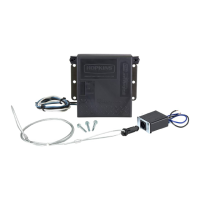
EasyManua.ls Logo

Hopkins Agility 47295 - User Manual

Default Icon
2 pages
Print Icon
To Next Page IconTo Next Page
Loading...
Agility
TM
Electronic Brake Control
Part No. 47295
IMPORTANT: Read the following instructions carefully before
installing and/or operating the brake control. If you have any
concerns with this product or the installation process, our technical
support team can assist you. Call (03) 9761 1110
A. Vertical slide for
manual override
B. Digital readout
display
C. Sensitivity adjustment
button
D. Digital power setting
buttons
E. Mounting bracket
holes
INSTALLATION PRECAUTIONS:
• Braking capacity is for 2, 4 or 6 trailer brake applications.
• This brake control will apply the trailer brakes while in reverse.
• This brake control is inertia activated. When the vehicle is not moving,
the brake control will not automatically apply the trailer brakes. In this
event, the vertical slide must be depressed to actuate the brakes.
This brake control is not reverse polarity protected. Reversing the
connection to the vehicle battery or the breakaway battery on the trailer
will damage the brake control.
Do not mount or activate RF (radio frequency) generating devices near
the brake control (less than 40cm proximity), i.e. Mobile phones,
two-way radios.
This brake control is designed to operate with electric trailer brakes and
not electric-hydraulic brake systems.
INSTALLATION GUIDE:
The brake control can be
mounted from –20 degrees
nose down to +70 degrees
nose up and parallel to the
direction of travel.
1. Mount the bracket to a secure location with
Phillip screws provided (A) where you will be
able to view the display and easily access
the vertical slide.
2. Attach the brake control to the bracket using the slotted hex screws provided (B).
3. Adjust the brake control to the desired angle and tighten screws until snug.
CAUTION: Drilling or using larger/longer screws may damage the unit.
WIRING GUIDE:
White wire - ground/negative terminal (-) on battery
Blue wire - trailer electric brakes
Black wire - positive terminal (+) on battery
Red wire - cold side of stop lamp switch or brake light
CAUTION: Wire colours vary by manufacturer. Be sure to wire by function only.
1. Be sure to use proper wire gauge when installing your control (12 gauge for
electric brakes and positive power, 16 gauge for the stop lamp switch and ground).
2. Connect the white wire directly to the negative post on the vehicle battery.
Grounding to any other location may cause intermittent brake control operation
or failure.
3. Attach 20-amp circuit breaker (for 6 brake use 30-amp) or in-line fuse to the
positive terminal on the vehicle’s battery.Route black wire from the brake control
to the fuse or breaker.
4. Splice the red wire into the cold side of the vehicle’s stop lamp switch located by
the brake pedal.Find the wire by using a circuit tester and probing for the wire
that powers the vehicle stop lamps when the brake pedal is pressed.
5. Route the blue wire from the brake control to the vehicle side towing connector
at the rear of the tow vehicle.
DIRECTION OF
TRAVEL
+70
0
-20
0
DIRECTION OF TRAVEL
CORRECT INCORRECT
CORRECT INCORRECT
A
B
A
B
C
D
E
OPTION: If your vehicle came equipped with a factory tow package, brake
control function wires may exist under the vehicle dash.Consult vehicle manual.
Simply splice the wires from the brake control to the function wires under the dash.
Front view of trailer plugs:
ELECTRIC WIRING
Trailer wiring must meet the following requirements:
• All wiring must be anchored to the chassis at intervals of not more than 600
millimetres along its length
• All wiring must be insulated at joints
• All wiring must be located in such a position that it can neither become
overheated nor contact moving parts
• All wiring must be protected from chafing
• An earth return wire must be provided between the trailer and its hauling
vehicle; it is not acceptable to use the trailer coupling as an earth.
AUSTRALIAN TRANSPORT SAFETY BUREAU
(DOTARS) TECHNICAL REQUIREMENTS
Trailers and towing vehicles must have electrical connectors which comply
with Australian Standard 2513-1982 'Electrical Connectors for Trailer
Vehicles' or as amended from time to time. Three types of seven pin
connectors are specified in the Standard and their wiring is shown below.
Twelve pin connectors are also specified in the Standard.
Note: Because of interchangeability problems that may arise it is
recommended that pin 5 in the 7 pin connectors be used only for service
brakes. If auxiliary circuits are required then the 12 pin type 3 connector
would be preferable.
7
Pin
Connector
12
Pin
Connector
Circuit Circuit Conductor
Circuit Conductor
Colour
1 Left-hand turn Yellow
2 Reversing Signal Black
3 Earth Return White
4 Right-hand turn Green
5 Service Brakes Blue
6 Stop Lamps Red
7 Rear Lamps, clearance and side Brown
marker Lamps
8 Battery Charger/Electric Winch Orange
9 Auxiliaries, etc. /Battery Feed Pink
10 Earth Return White
11 Rear Fog Lamp Grey
12 Spare Violet
TYPE 3
1 2
3
4
7
6
5
1 2
3
4
7
6
5
8
11
12
9
10
TYPE 1
1
2
3
4
7
6
5
20mm
TYPE 2
1
2
3
4
7
6
5
13mm
Question and Answer IconNeed help?

Do you have a question about the Hopkins Agility 47295 and is the answer not in the manual?

Summary

INSTALLATION PRECAUTIONS

INSTALLATION GUIDE

WIRING GUIDE

Details specific wire connections for the brake control unit to the vehicle.

AUSTRALIAN TRANSPORT SAFETY BUREAU (DOTARS) TECHNICAL REQUIREMENTS

ELECTRIC WIRING REQUIREMENTS

Specific safety and installation requirements for electric trailer wiring as per DOTARS.

OPERATING AND SETTING YOUR CONTROLLER

TESTING AND ADJUSTING BRAKING RESPONSE

Overview

The Agility™ Electronic Brake Control, Part No. 47295, is a device designed to manage electric trailer brakes. It is suitable for 2, 4, or 6 trailer brake applications and operates on an inertia-activated principle, meaning it will not automatically apply trailer brakes when the vehicle is stationary unless the vertical slide is depressed. The unit is not reverse polarity protected, so incorrect connection to the vehicle or breakaway battery can damage it.

Technical Specifications and Features:

  • Braking Capacity: Supports 2, 4, or 6 trailer brake applications.
  • Inertia Activation: Applies trailer brakes based on vehicle deceleration.
  • Reverse Braking: The brake control will apply trailer brakes while the vehicle is in reverse.
  • Mounting Angle: Can be mounted from -20 degrees nose down to +70 degrees nose up, parallel to the direction of travel.
  • Display: Features a digital readout display (B) to show power settings and indicate trailer connection or short circuit.
  • Manual Override: Equipped with a vertical slide (A) for manual brake application.
  • Sensitivity Adjustment: A button (C) allows adjustment of the trailer braking response from least sensitive (setting 1) to most sensitive (setting 5).
  • Digital Power Setting: Buttons (D) adjust the power sent to the trailer brakes, displayed as a percentage from 5% to 99% in 5% increments.
  • Short Circuit Indication: The display will show "SC" if a short circuit occurs.
  • Compatibility: Designed for electric trailer brakes only, not electric-hydraulic brake systems.
  • RF Interference: Should not be mounted or activated near RF-generating devices (e.g., mobile phones, two-way radios) within 40cm proximity.

Installation Guide:

  1. Mounting: Secure the provided bracket using Phillips screws (A) in a location where the display is visible and the vertical slide is easily accessible.
  2. Attachment: Attach the brake control to the bracket using the slotted hex screws (B).
  3. Adjustment: Adjust the brake control to the desired angle and tighten screws until snug. Drilling or using larger/longer screws than provided may damage the unit.

Wiring Guide:

  • Wire Colors (Standard):
    • White wire: Ground/negative terminal (-) on battery.
    • Blue wire: Trailer electric brakes.
    • Black wire: Positive terminal (+) on battery.
    • Red wire: Cold side of stop lamp switch or brake light.
    • Note: Wire colors may vary by manufacturer; always wire by function.
  • Wire Gauge: Use 12 gauge for electric brakes and positive power, and 16 gauge for the stop lamp switch and ground.
  • Ground Connection: Connect the white wire directly to the negative post on the vehicle battery. Grounding to other locations may cause intermittent operation or failure.
  • Power Connection: Attach a 20-amp circuit breaker (or 30-amp for 6 brakes) or in-line fuse to the positive terminal on the vehicle's battery. Route the black wire from the brake control to this fuse or breaker.
  • Stop Lamp Switch Connection: Splice the red wire into the cold side of the vehicle's stop lamp switch, located by the brake pedal. Use a circuit tester to find the wire that powers the vehicle stop lamps when the brake pedal is pressed.
  • Trailer Connector: Route the blue wire from the brake control to the vehicle-side towing connector at the rear of the tow vehicle.
  • Factory Tow Package Option: If the vehicle has a factory tow package, consult the vehicle manual for existing brake control function wires under the dash and splice the brake control wires to them.

Australian Transport Safety Bureau (DOTARS) Technical Requirements for Electric Wiring:

  • Anchoring: Wiring must be anchored to the chassis at intervals not exceeding 600 millimeters.
  • Insulation: All wiring must be insulated at joints.
  • Positioning: Wiring must be located to prevent overheating or contact with moving parts.
  • Protection: All wiring must be protected from chafing.
  • Earth Return: An earth return wire must be provided between the trailer and its hauling vehicle; the trailer coupling is not acceptable as an earth.

Trailer Electrical Connectors (Australian Standard 2513-1982):

  • 7-Pin Connectors:
    • Pin 1: Left-hand turn (Yellow)
    • Pin 2: Reversing Signal (Black)
    • Pin 3: Earth Return (White)
    • Pin 4: Right-hand turn (Green)
    • Pin 5: Service Brakes (Blue) - Recommended for service brakes due to interchangeability issues.
    • Pin 6: Stop Lamps (Red)
    • Pin 7: Rear Lamps, clearance and side marker Lamps (Brown)
  • 12-Pin Connectors:
    • Pin 8: Battery Charger/Electric Winch (Orange)
    • Pin 9: Auxiliaries, etc./Battery Feed (Pink)
    • Pin 10: Earth Return (White)
    • Pin 11: Rear Fog Lamp (Grey)
    • Pin 12: Spare (Violet)
    • Note: For auxiliary circuits, the 12-pin Type 3 connector is preferable.

Operating and Setting the Controller:

  1. Trailer Connection: A red dot on the bottom right of the digital display indicates a connected trailer. A blank display (no dot) indicates no trailer is connected.
  2. Power Adjustment: Use the (+/-) buttons to adjust power from 5% to 99%.
  3. Sensitivity Adjustment: Use the "S" button to adjust sensitivity from 1 (least sensitive) to 5 (most sensitive).
  4. Short Circuit: The display shows "SC" if a short circuit occurs.

Testing and Adjusting Braking Response:

  1. Initial Test: Connect to the trailer and test drive in a dry, open area at 30-40 kph, applying vehicle brakes aggressively.
  2. Lock-up Adjustment: If trailer brakes lock-up, reduce the power setting using the (-) button.
  3. Pushing Adjustment: If the trailer feels like it's pushing the tow vehicle, increase the power setting using the (+) button.
  4. Sensitivity Adjustment: Start with a sensitivity setting of 3. Reduce by 1 if brakes come on too early; increase by 1 if brakes come on too slowly.
  5. Repeat the process until smooth braking is achieved.

Hopkins Agility 47295 Specifications

General IconGeneral
BrandHopkins
ModelAgility 47295
CategoryAutomobile Accessories
LanguageEnglish

Related product manuals