3
2-2 Mass flow meter(SEF-E431X/SEF-E441X)
Type *1 SEF-E431X SEF-E441X
Standard flow rate range *2
(Full scale flow rate equivalent to N
2
)
50 / 100 SLM 200 SLM
Accuracy *3,*4
±1.0% F.S.
Operating temperature
5〜45℃
Linearity *3
Within ±0.5% of F.S.
Repeatability *3
Within ±0.5% of F.S.
Operating differential pressure *5 Less than 300 kPa (D)
Maximum operating pressure *5 350 kPa (G)
Pressure resistance *5 1000 kPa (G)
Leak integrity *6
1×10
-9
Pa・m
3
/sec (He) or less
Output signal
0〜5V DC (Minimum load resistance 2kΩ)
Power source
+15V DC±5% 50mA , –15V DC±5% 200mA
Wetted material Stainless steel, Fluoro rubber
Standard fittings 3/8inch Swagelok or equivalent
*1:This product is in conformity with RoHS directives.
*2:SLM denotes gas flow rate in l/min.
*3:Accuracy, linearity and repeatability are guaranteed for the calibration gas.
*4:Temperature for accuracy guarantee is in accordance with SEMI standard E56−1296.
*5:(D) indicates differential pressure. (G) indicates gauge pressure.
*6:
Mechanical leak rate (SEMI standard E16−90).
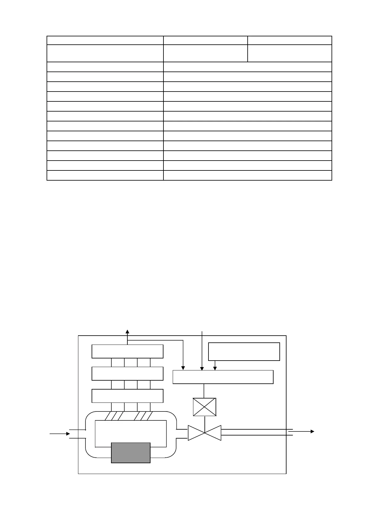
3. Principle of Functioning
The mass flow controller consists of a flow rate sensor, control valve, control circuit, etc.
If the gas flows, there will be a temperature difference between the upstream and down stream
of the sensor section, providing an output proportional to a mass flow rate.
Comparing this output with an external setting signal, the mass flow controller automatically
adjusts the opening of the valve so that the signal will match.
Sensor
Control Valve
Flow Rate Signal Output
(0〜5V DC )
Flow Rate Setting Signal
Input ( 0.25〜5V DC )
Comparison Control Circuit
Bridge Circuit
Bypass
Gas
mplifier Circuit
Correction Circuit
Power source of
Control Valve