Do you have a question about the Horizon Hobby Slow Stick and is the answer not in the manual?
Attaching horizontal stabilizer and elevator using transparent stick tape.
Joining the fuselage boom sections using a plastic connector.
Positioning receiver, ESC, and battery pack on the boom.
Attaching wheels to the main and tail landing gear assemblies.
Attaching the main landing gear to its designated mount.
Installing the tail wheel landing gear assembly.
Applying adhesive to the front of the boom for the motor mount.
Securing the motor mount to the front of the boom.
Creating a dihedral angle by folding wing halves and taping them.
Attaching control horns to the elevator and rudder surfaces with glue.
Placing the elevator and rudder servos into their mounting holes.
Step-by-step guide for securely mounting servos using grommets and screws.
Creating "V" bends in push rods for fine-tuning control linkage length.
Inserting the push rod ends into the servo horn holes.
Marking the push rod length based on servo shaft center.
Defining the CG range and its effect on flight stability and sensitivity.
Step-by-step guide for initiating flight, including pre-flight checks and initial climb.
Step-by-step guide for bringing the aircraft safely to the ground.
| Brand | Horizon Hobby |
|---|---|
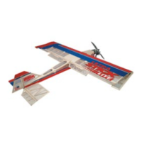
| Model | Slow Stick |
| Category | Toy |
| Language | English |