EasyManua.ls Logo

Hotpoint FF187EG User Manual

Hotpoint FF187EG
36 pages
To Next Page IconTo Next Page
Page #1 background imageLoading...
Page #1 background image
Indesit Company UK Ltd
© 2009 Reg. Office: Peterborough PE2 9JB Registered in London: 106725
Service
Information
HOTPOINT
Freestanding
Frost Free
Fridge Freezers
(Version 2)
Refer to Insert below
Models Comm.
Covered Code
FF187EA 40729
FF187EG 39780
FF187EK 53950
FF187EP 39775
FF187EPL 53947
FF200EA 40733
FF200EG 40732
FF200EX 43503
FF200EK 53952
FF200EP 39777
FF200EPL 53949
IMPORTANT
THERE ARE TWO VERSIONS OF THE
ABOVE LISTED MODELS. TO IDENTIFY THE
CORRECT VERSION AND SERVICE
MANUAL SEE BELOW OR Page 5 FOR A
MORE DETAILED EXPLANATION:
VERSION 1 ~
THE POWER MODULE IS MOUNTED AT THE
REAR OF THE APPLIANCE ABOVE THE
COMPRESSOR COMPARTMENT.
VERSION 2 ~
THE POWER MODULE IS MOUNTED IN THE
CONTROL PANEL ONLY, THERE IS NO
REAR MOUNTED MODULE.
FOR VERSION 1 MODELS ~ REFER TO
SERVICE MANUAL 5407327
5407423 Issue 1 Feb. 2009
Question and Answer IconNeed help?

Do you have a question about the Hotpoint FF187EG and is the answer not in the manual?

Hotpoint FF187EG Specifications

General IconGeneral
Energy RatingA+
Dimensions (H x W x D)187.5 x 59.5 x 65.5 cm
Weight50 kg
Appliance placementFreestanding
Freezing capacity10 kg/24h
Climate classSN, N, ST, T
Door hingeRight
Reversible doorsYes
Energy efficiency classA+
Defrost SystemManual
Total Capacity187 liters
Freezer net capacity187 liters
Storage time during power failure12 hours
Star rating4 Star
Width60 cm

Summary

PRODUCT IDENTITY

Industrial Code

Identifies the industrial code for model information and system identification.

Commercial Code

Vital for correct model information and system identification.

Serial Number

Provides details about the appliance's build date and number.

MODEL VERSION IDENTIFICATION

VERSION 1

Details the power module location for Version 1 models.

VERSION 2

Details the power module location for Version 2 models.

MODEL INTRODUCTION

FF187E interior

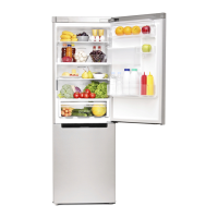
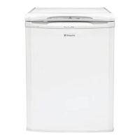
Describes the interior features and layout of the FF187E model.

FF200E interior

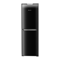
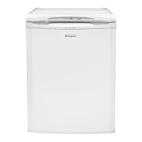
Describes the interior features and layout of the FF200E model.

ANTI-BACTERIA (Hygiene Control)

Explains the anti-bacteria protection feature for food safety.

SPECIFICATIONS

GENERAL

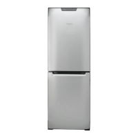
Provides general manufacturing and appliance type information.

DIMENSIONS & WEIGHT

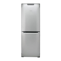
Lists the physical dimensions and weight of the appliance models.

CAPACITIES / VOLUME

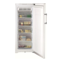
Details the storage capacities and freezing capabilities of the models.

TECHNICAL DATA

COMPRESSOR WINDINGS

Provides technical specifications for compressor windings.

HEATER RESISTANCES

Lists the resistance values for heating elements.

DESCRIPTION OF APPLIANCE

REFRIGERATOR OPERATION Knob

Explains the function of the refrigerator temperature control knob.

SUPER COOL Button

Describes the quick cool function and its indicator light.

FREEZER OPERATION Knob

Explains the function of the freezer temperature control knob.

SUPER FREEZE Button

Describes the fast freeze function and its indicator light.

COMPONENT FUNCTION

General Information

Overview of the power module's structure and function.

Fridge & Freezer Control

How the power module manages fridge and freezer sensors and cooling.

Freezer Evaporator Fan Module

Function and control of the freezer evaporator fan.

Electronic Motorised Damper Assembly (Baffle)

Purpose and operation of the motorised damper for air distribution.

AUTO-TEST

FAULT CONDITIONS

AIR FLOW

DUCT PANEL AIR FLOW

POWER / CONTROL MODULE Parameters

COMPRESSOR OPERATION

Details situations where the compressor remains off.

POWER/CONTROL MODULE Parameters

DEFROST AND DRIP TRAY HEATING ELEMENTS

Parameters for starting and ending defrost cycles.

FREEZER FAN OPERATION

How the freezer fan is managed by the power module.

FRIDGE LAMP OPERATION

Control of interior lamps based on door status.

FAULT DIAGNOSIS QUICK GUIDE

SERVICING & DISMANTLING INSTRUCTIONS

A. Removing the Fridge Door

Steps to remove the fridge door.

B. Removing the Freezer Door

Steps to remove the freezer door.

C. Control Panel (housing the Power / Control module)

Instructions to access the control panel and module.

D. POWER / CONTROL Module

Procedure to remove the power/control module.

SERVICING & DISMANTLING INSTRUCTIONS

J. Damper (Baffle) Unit (Motorised Type)

Steps to remove the motorised damper unit.

K. Freezer Fan Motor

Procedure to remove the freezer fan motor.

PROGRAMMING THE POWER MODULE

METHOD 1 - Indesit ENGINEERS ONLY

METHOD 2 - SMARTCARD - SUITABLY QUALIFIED PERSONS ONLY

SMARTCARD PROGRAMMING PROCEDURE - FLOWCHART

CONNECTING THE LOW END ADAPTOR - 2007 Version

WIRING CONNECTION CHART

POWER / CONTROL MODULE EDGE CONNECTIONS

THEORETICAL WIRING DIAGRAM

THERMISTOR SENSOR LOCATIONS

DOOR REVERSAL

A: Reversing the Top Hinge

Steps for reversing the top hinge.

B: Front Base Moulding (Plinth)

Instructions for handling the front base moulding/plinth.

C: Reversing the Top Hinge Bushes and Door Stops

Steps to reverse top hinge bushes and door stops.

D: Top Hinge Pin and Door Assembly

Procedure for fitting the top hinge pin and door.

Related product manuals