Do you have a question about the Hotpoint FF200EP and is the answer not in the manual?
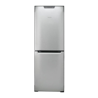
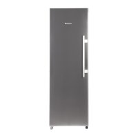
Lists the specific Hotpoint fridge freezer models covered by this manual and their commercial codes.
Explains how to identify Version 1 and Version 2 models based on power module location.
Safety precautions for handling Isobutane R600a refrigerant during servicing operations.
Guidelines for storing, dispensing, and handling Isobutane refrigerant canisters safely.
Explains the format and meaning of the appliance's industrial code for identification.
Explains the format and meaning of the appliance's serial number for identification.
Details how to identify Version 1 models using serial number and power module location.
Details how to identify Version 2 models using serial number and power module location.
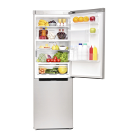
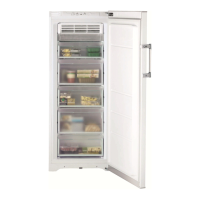
Describes the interior components and layout of the FF187E fridge freezer model.
Describes the interior components and layout of the FF200E fridge freezer model.
Explains the anti-bacterial protection for food safety and odour reduction.
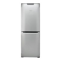
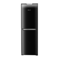
Covers manufacturing, type, frost, doors, and plug/cable specifications.
Provides height, width, depth, and weight for FF187E and FF200E models.
Details gross/net capacities and freezing capabilities for FF187E and FF200E.
Lists compressor manufacturer, type, and winding resistances.
Details resistance values for evaporator defrost and gutter heaters, and thermal fuse.
Illustrates and labels the various parts of the appliance interior.
Explains operation of knobs, buttons, and indicator lights on the control panel.
Explains the structure and function of the power module and its memory.
Details how the power module monitors sensors and controls cooling functions.
Describes the function and control of the freezer evaporator fan.
Explains the purpose and control of the motorised damper (baffle).
Details compressor protection, long activity periods, and post-defrost pause.
Explains LED status for Super Cool, Mains, Super Freeze, and Audible Bleep for alarms.
Step-by-step instructions for initiating and ending the auto-test sequence.
Explains how to check for faults based on LED behaviour and component operation.
Lists fault codes derived from LED patterns during auto-test.
Explains causes and corrective actions for fault codes F01 through F06.
Explains causes and corrective actions for fault codes F07, F09, F14, F20-F24.
Explains cause and corrective action for fault code F25 (Evaporator NTC sensor).
Illustrates how cold air enters the fridge via the multi-flow unit when the damper opens.
Illustrates how air returns to the freezer section via the exhaust grille.
Shows how air is drawn through the evaporator and distributed via duct panels.
Explains how stored parameter values direct appliance functions based on sensor readings.
Details conditions preventing compressor start, including protection and pauses.
Outlines parameters that start/end defrost, including heater ON time.
Explains how the power module manages freezer fan operation and timing.
Describes power module control of interior lamps, including flashing for door alerts.
Provides causes and actions for interior light flashing and warm fridge temperature.
Lists causes and actions for freezer fan not running and freezer temperature warm.
Addresses compressor not running (with/without lamp) and normal operating sounds.
Step-by-step guide for removing fridge/freezer doors and the control panel.
Instructions on how to remove and replace the power/control module.
Details removal of door seals, interior lamps, and the fridge multi-flow unit.
Instructions and diagrams for reversing the appliance door hinges.
Guides for removing the motorised damper unit and the freezer fan motor.
Explains that replacement modules are un-programmed and require specific software.
Step-by-step guide for programming using PC/Hand-Held, USB lead, and hardware key.
Details programming using a Smart Card, Smart Reader, and Low End Adaptor.
Flowchart illustrating the steps and decision points for smart card programming.
Step-by-step instructions on how to connect the 2007 version Low End Adaptor.
Details pin assignments for defrost heater and thermal fuse connection plugs and sockets.
Shows alternative connection socket pin assignments for various components.
Lists wire colours and components for terminal block E1 on the power module.
Lists wire colours and components for terminal block E2 on the power module.
Lists wire colours and components for IDC connections E4 (thermistor sensors).
Lists wire colours and components for IDC connections E3 (compressor harness).
Shows the theoretical wiring layout from the power control module to key components.
Describes the approximate locations of the freezer air, evaporator, and fridge air sensors.
Provides a table correlating temperature with resistance values for thermistor sensors.
Instructions for removing and transferring the top hinge for door reversal.
Details removing and refitting the plinth for door reversal.
Covers reversing door stops and transferring hinge bushes.
Guides for reassembling doors and hinges after reversal.