3:14 PM Refrig-GF & SR 2/10/2012
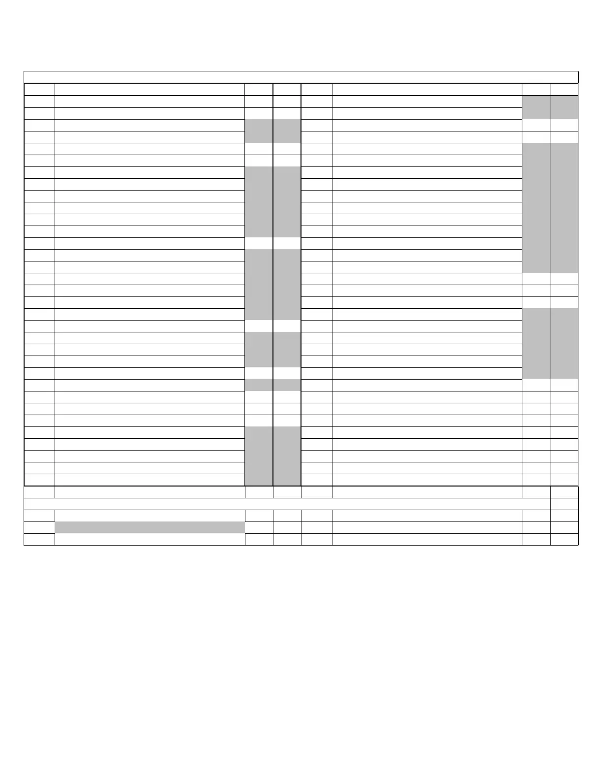
Label Name Set-F Set-C Label Name Set-F Set-C
Set Set Point 35 2 dAF Defrost delay after fast freez 0.0 0.0
Hy Differential 4 2 ALc Temp. alarm configuration Ab Ab
LS Min Set Point 30 -1 ALU MAX. temperature alarm 45 7
US Max. Set Point 45 7 ALL MIN. temperature alarm 32 0
Ot Thermo Probe Calibration 0 0 AFH Diff for temp. alarm recovery 1 1
P2P Evap. Probe Presence Y Y ALd Temp. alarm delay 10 10
OE Evap. Probe Calibration 0 0 dAO Delay of temp alarm at start up 0.2 0.2
P3P Third Probe Presence n n AP2 Probe for temp. alarm of cond P4 P4
O3 Third Probe Calibration 0 0 AL2 Cond for low temp alarm -4 -4
P4P Fourth Probe Presence n n AU2 Cond for high temp alarm 23 23
O4 Fourth Probe Calibration 0 0 AH2 Diff for cond. Temp alarm rec 1 1
OdS Output Delay - Start Up 1 1 Ad2 Cond temp alarm delay 15 15
AC Anti-Short Cycle Delay 1 1 dA2 Delay of cond temp alarm start up 1.3 1.3
rtr P1-P2 Percentage 100 100 bLL Comp off for cond low temp alarm n n
CCt Continuous Cycle Duration 0 0 AC2 Comp off for cond high temp alarm nn
CCS Set Point - Continuous Cycle 0 0 i1P Digital input polarity CL CL
COn Comp. ON - Faulty Probe 4 4 i1F Digital input configuation EAL EAL
COF Comp. OFF - Faulty Probe 6 6 did Digital input alarm delay 5 5
CF Temp. Measure Unit F C Nps Number of act of pressure switch 15 15
rES Resolution in in odc Compress status when open dr no no
Lod Probe Display P3 P3 rrd Regulation restart with DR open alarm y y
dLy Display Temp Delay 0 0 HES Differential for energy saving 0 0
dtr P1-P2 Percentage for Display 50 50 Adr Serial address 1 1
tdF Defrost Type EL EL PbC Kind of probe NTC NTC
dFP Probe Selection Defrost Term P2 P2 onF on/off key enabling no no
dtE Defrost Term Temp. 40 4 dP1 Room probe display -- --
IdF Interval Between Defrost Cycle 24 24 dP2 Evaporator probe display -- --
MdF Max. Length for Defrost time 60 60 dP3 Third probe display -- --
dSd Start defrost delay 0 0 dP4 Fourth probe display -- --
dFd Displaying during defrost it it rSE Valore set operativo -- --
dAd MAX display delay after def. 10 10 rEL Software release 1.0 1.0
Fdt Draining time 0 0 Ptb Map code -- --
dPO First defrost after startup n n BOLD Pr2
GR Series
BOLD = PARAMETER 2 GSR Series
SR Series
TO SEE SET POINT TEMPERATURE, PRESS SET KEY AND RELEASE TO DISPLAY SET POINT
Control Factory (F-C) Settings February 10, 2012 XR40CX- (21-376)
1 of 1 XR40CX-HM Refrigerator (F-C) Setting 111206.xls
 Loading...