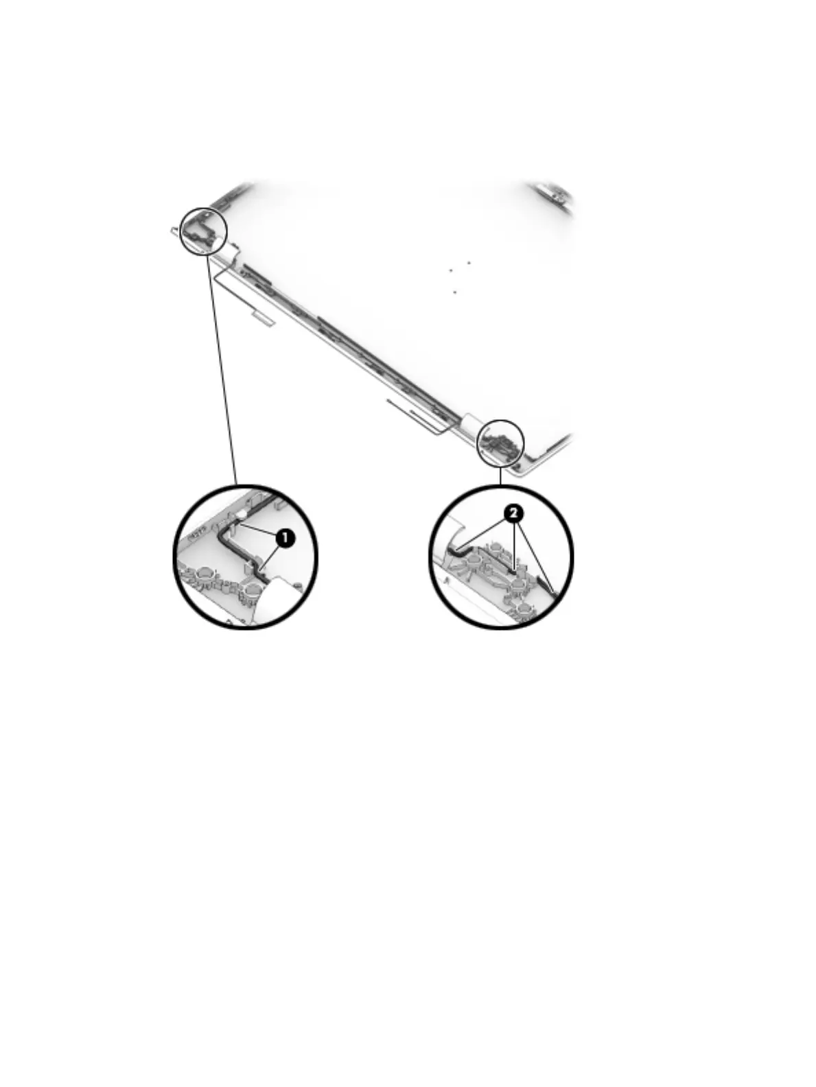
8. Use the following image to determine proper cable routing around the left hinge for the camera/display
cable and the wireless antenna cables.
(1): Display/camera cable routing path
(2): Antenna cable routing path
9. If replacing the display enclosure, be sure that the subcomponents (including the camera/microphone
module, the antenna receivers, and all associated cables and hardware) are transferred to the new
enclosure.
Reverse this procedure to reassemble and install the display assembly.
Component replacement procedures 65
 Loading...