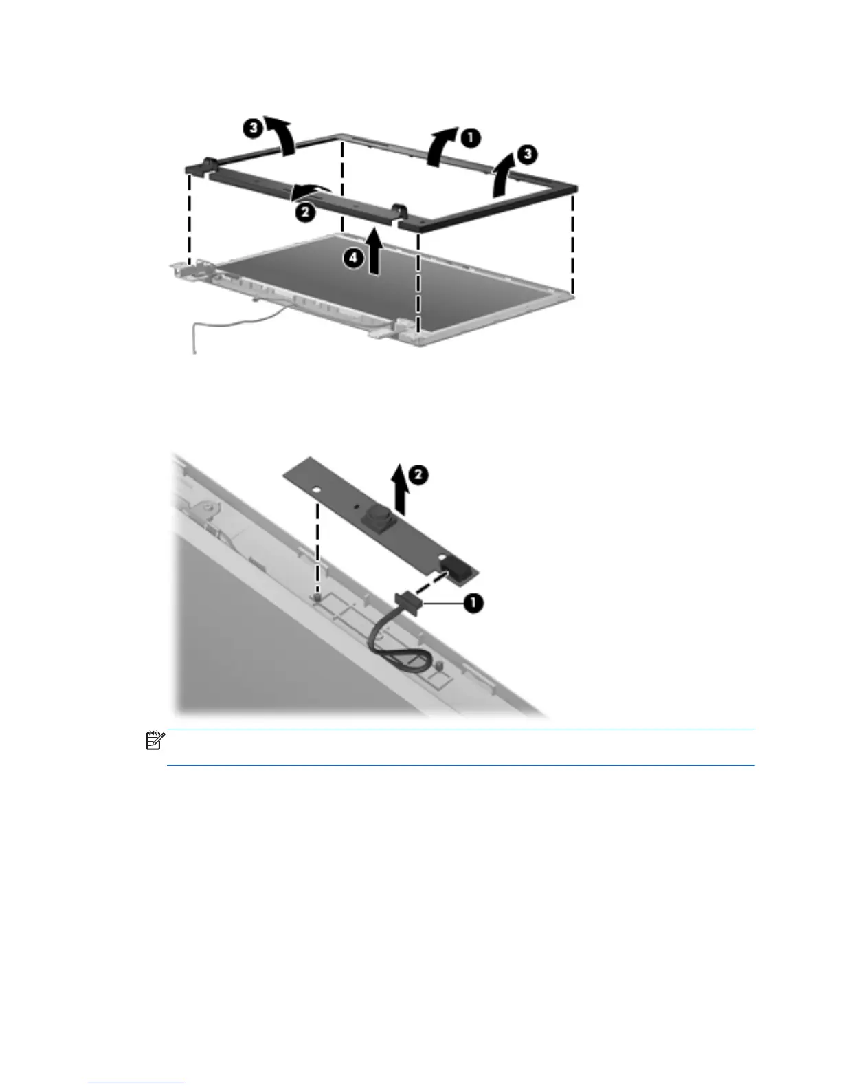
3.
Lift the bezel (4) from the display enclosure.
4. If it is necessary to replace the webcam module, disconnect the webcam cable from the module
(1), and pull the webcam module (2) that is attached with adhesive off the display enclosure. The
webcam module can be ordered by using spare part number 611026-001.
NOTE: To replace the webcam module in the display enclosure, align the holes on the webcam
module with the pins on the display enclosure and press onto the double-sided tape.
5. If it is necessary to replace the display hinges, remove the six Torx M2.5×6.0 screws (1) that
secure the display panel to the display enclosure.
92 Chapter 4 Removal and replacement procedures
 Loading...