EasyManuals Logo

HP 33120A Installation Instructions

HP 33120A
6 pages
To Next Page IconTo Next Page
To Previous Page IconTo Previous Page
Page #3 background imageLoading...
Page #3 background image
2 Carefully cut two holes in the rear-panel label.
The Ref Out and Ext Ref In terminals on the Phase-Lock assembly will
extend through these holes in the
HP 33120A rear-panel.
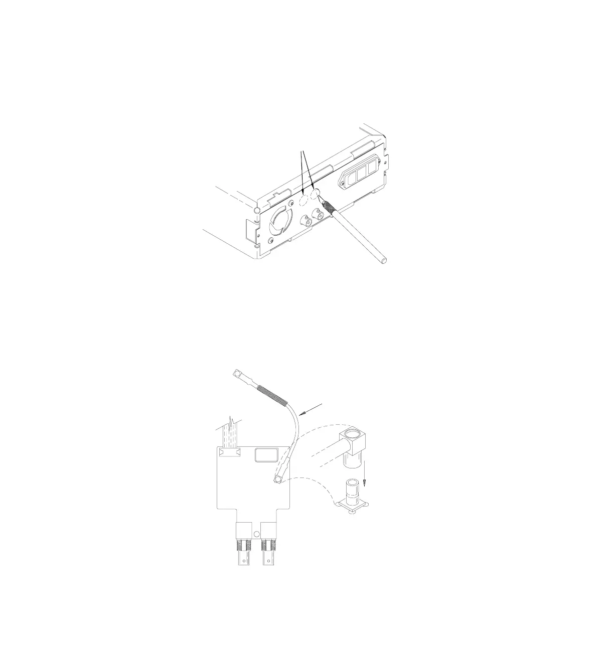
3 Connect the coaxial cable to the Phase-Lock circuit board.
Connect one end of the coaxial cable (included with the retrofit kit) to
the connector labeled P2 on the Phase-Lock circuit board. Position the
cable as shown.
2
Cut Out Holes
Coaxial Cable (33120-61603)
P2
P2

Other manuals for HP 33120A

Questions and Answers:

Question and Answer IconNeed help?

Do you have a question about the HP 33120A and is the answer not in the manual?

HP 33120A Specifications

General IconGeneral
Frequency Range100 µHz to 15 MHz
WaveformsSine, Square, Triangle, Ramp, Arbitrary
Amplitude Range10 mVpp to 10 Vpp into 50 Ohms
Output Impedance50 Ohms
InterfaceGPIB
Function Generator TypeArbitrary
Power Requirements100/120/220/240 VAC ±10%, 50/60 Hz, 60 VA max

Related product manuals