EasyManuals Logo

HP 33120A Installation Instructions

HP 33120A
6 pages
To Next Page IconTo Next Page
To Previous Page IconTo Previous Page
Page #4 background imageLoading...
Page #4 background image
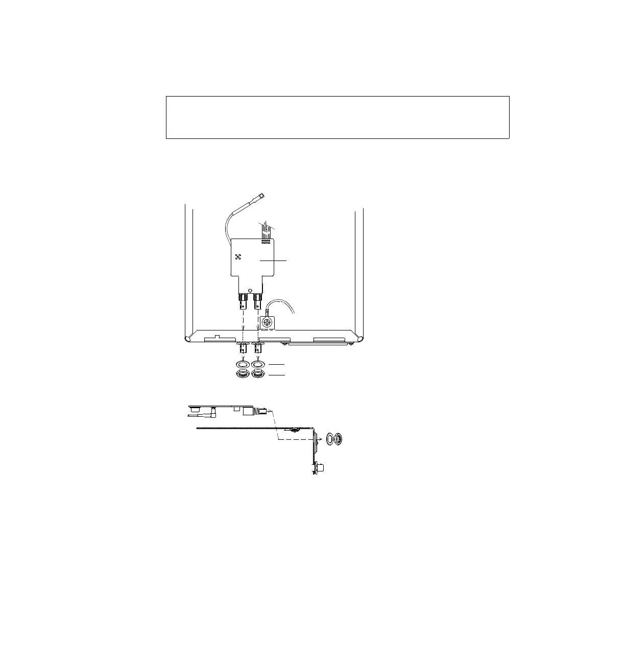
4 Install the Phase-Lock assembly in the
HP 33120A chassis.
Before installing the Phase-Lock assembly, make sure that the red and
black wires for the instrument fan are clear of the rear-panel holes.
With the Phase-Lock assembly positioned trace side up, insert the two
BNC connectors through the holes previously cut in the rear-panel label.
5 Secure the Phase-Lock assembly in place.
As shown above, place one lock washer and one hex nut (included with
the retrofit kit) on each of the two
BNC connectors. To prevent cross-
threading, be sure to hand-tighten the hex nuts at least one turn before
using a tool.
3
Lock Washer (2190-0699)
Hex Nut (2940-0256)
Trace Side Up
Top View
Side View

Other manuals for HP 33120A

Questions and Answers:

Question and Answer IconNeed help?

Do you have a question about the HP 33120A and is the answer not in the manual?

HP 33120A Specifications

General IconGeneral
Frequency Range100 µHz to 15 MHz
WaveformsSine, Square, Triangle, Ramp, Arbitrary
Amplitude Range10 mVpp to 10 Vpp into 50 Ohms
Output Impedance50 Ohms
InterfaceGPIB
Function Generator TypeArbitrary
Power Requirements100/120/220/240 VAC ±10%, 50/60 Hz, 60 VA max

Related product manuals