General Information
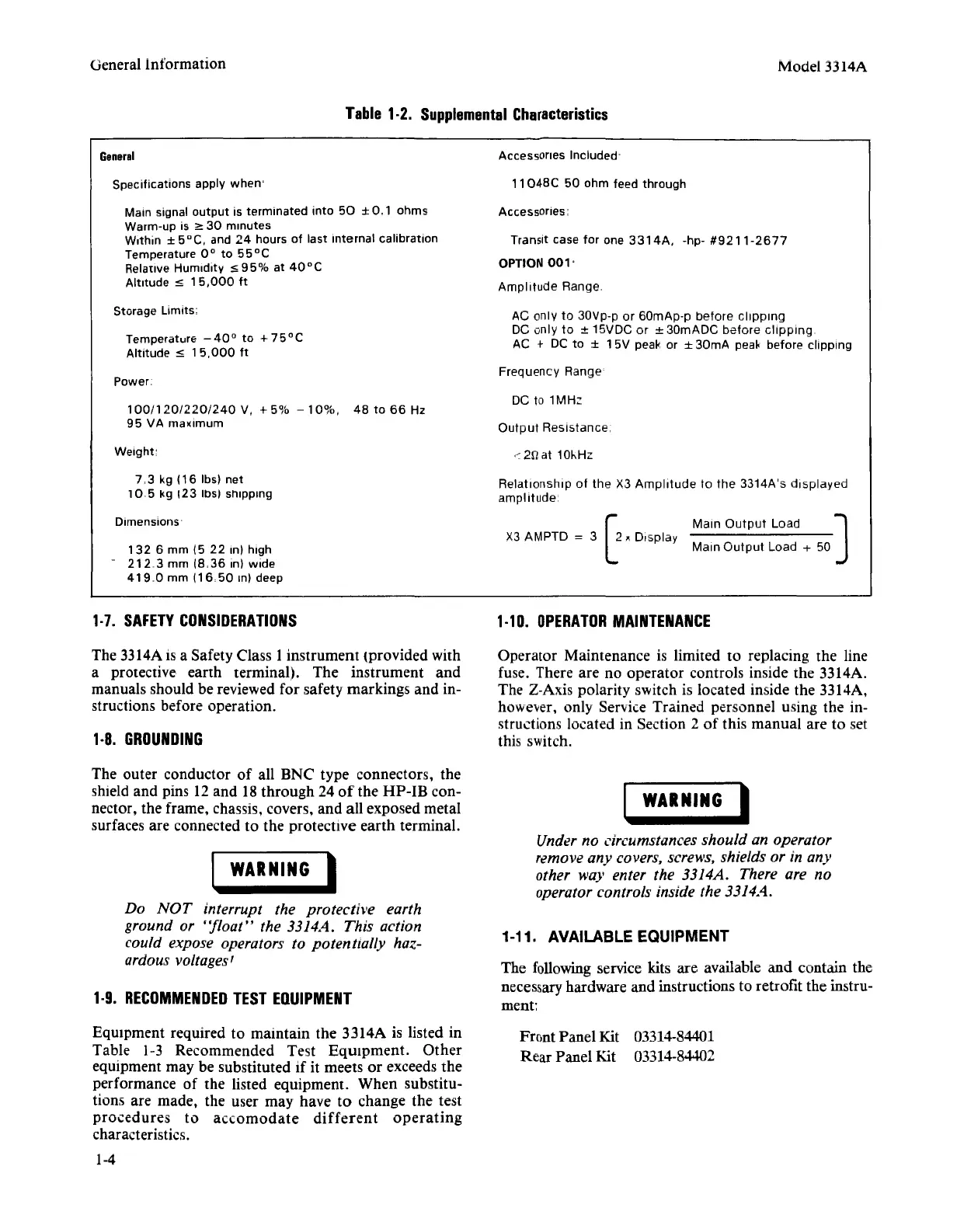
General
Table
1·2.
Supplemental
Characteristics
Acceasones included-
Model 3314A
Specifications apply when:
Main signal
output
IS
terminated
Into
50
± 001
ohms
Warm-up is :2: 30 minutes
W,thin ±
5°C,
and
24
hours of last Internal calibration
Temperature
0°
to
55°C
Relative
Humiditv
:s
95%
at
40°C
Altitude :s
15,000
ft
Storage
limits:
Temperature -
40
°
to
+
75
° C
Altitude :s 1
5,000
ft
Power
100/120/220/240
V, + 5% -
10%,
48
to
66
Hz
95 VA rnaxrrnurn
7,3
kg
(16
lbs) net
10
5 kg 123 ins) shipping
Dimensions
132
6 mm (5 22 In) high
-
21203mm(8,36,n)wide
41900
mm
(16050
In) deep
1·7.
SAFETY
CONSIDERATIONS
The 3314A is a Safety Class 1instrument (provided with
a protective earth terminal). The instrument and
manuals should be reviewed for safety markings and in-
structions before operation.
1·8.
GROUNDING
The outer conductor of all BNC type connectors, the
shield and pins 12and 18 through 24
of
the
HP-IB
con-
nector, the frame, chassis, covers, and
all
exposed metal
surfaces are connected to the protective earth terminal.
I
WARNING
I
Do
NOT
interrupt the protective earth
ground or
"float"
the 3314A. This action
could expose operators to potentially haz-
ardous voltages'
1·9.
RECOMMENDED
TEST
EQUIPMENT
Equipment required to maintain the 3314A is listed in
Table 1-3 Recommended Test
Equipment. Other
equipment may be substituted if it meets or exceeds the
performance of the listed equipment. When substitu-
tions are made, the user may have
to
change the test
procedures
to accornodate
different
operating
characteristics.
1-4
11048C
50 ohm feed through
Accessones:
Transit case
for
one
3314A,
-hp-
#9211-2677
OPTION
001'
Amplitude
Range
AC only to 30Vp-p or
60mAp-p
before
clipping
DC only
to
± 15VDC or ±
30mADC
before
clipping
AC + DC to ±
15V
peak or ±
30m
A peak before clipping
Frequency
Range
DC to
1MHz
Output
Resistance
,~2fl
at 10l-Hz
Relationship
of
the
X3
Amplitude
to
the
3314A's
displayed
amplitude
[
Main
Output
Load ]
X3 AMPTD = 3
2.
Display
.
Main
Output
Load + 50
1·10.
OPERATOR
MAINTENANCE
Operator Maintenance is limited
to
replacing the line
fuse. There are no operator controls inside the 3314A.
The Z-Axis polarity switch is located inside the 3314A,
however, only Service Trained personnel using the in-
structions located in Section
2
of
this manual are to set
this switch.
I
WARNING
I
Under no circumstances should an operator
remove any covers, screws, shields or in any
other way enter the 3314A. There are no
operator controls inside the 3314A.
1-11. AVAILABLE EQUIPMENT
The following service kits are available
and
contain the
necessary hardware and instructions to retrofit the instru-
ment:
Front Panel Kit
03314-84401
Rear
Panel Kit 03314-84402