Model 3314A
3314
UNIVERSAL
COUNTER
Performance Tests
L
l~
Lll
l[otlEJ
[L
L l
LI
(,.
...
....
...
...
LLLLLL
"
Il
L L
Lj
t.. ...
l.
.... ...
toI
LLLLLL
~
"~"II"
"",,]~
~~
L L L e @ L e
E;1\
L
=~
ItH
\
TRIG \
'-----------------------~
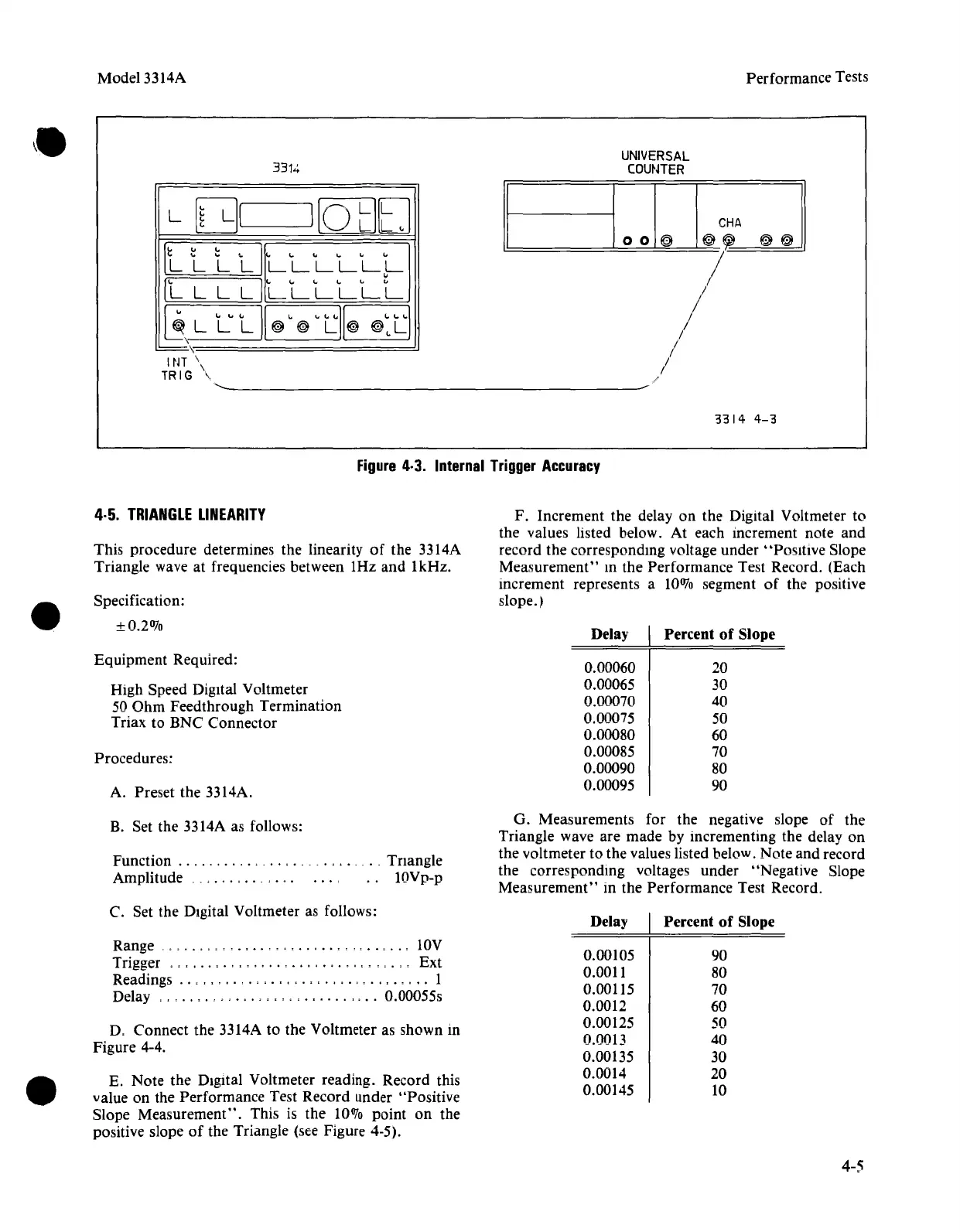
Figure
4·3.
Internal
Trigger
Accuracy
3314
4-0
F. Increment the delay on the Digital Voltmeter to
the values listed below. At each increment note and
record the corresponding voltage under
"Positive Slope
Measurement"
m the Performance Test Record. (Each
increment represents a
10070
segment
of
the positive
slope.)
4·5.
TRIANGLE
LINEARITY
This procedure determines the linearity
of
the 3314A
Triangle wave at frequencies between 1Hz and 1kHz.
Specification:
±0.21170
Equipment Required:
High Speed Digital Voltmeter
50
Ohm
Feedthrough Termination
Triax to BNC Connector
Procedures:
A. Preset the 3314A.
Delay
0.00060
0.00065
0.00070
0.00075
0.00080
0.00085
0.00090
0.00095
Percent
of
Slope
20
30
40
50
60
70
80
90
B. Set the 3314A as follows:
Function
....
, ,
..
, . ,
Amplitude
..
,.,.,
...
Triangle
lOVp-p
G. Measurements for the negative slope of the
Triangle wave are made by incrementing the delay on
the voltmeter to the values listed below. Note and record
the corresponding voltages under "Negative Slope
Measurement"
in the Performance Test Record.
C. Set the DIgital Voltmeter as follows:
Range
, , , , . ,
..
, , , ,
..
,
..
, ,
..
, IOV
Trigger
""""""""""""'"
, , . "
Ext
Readings '" , , , , . , . , , . , , , . , , . , , . , , . , , . , ,
..
1
Delay
",
..
,.",.,.""".,
....
,'
..
0.00055s
D, Connect the 3314A to the Voltmeter as shown in
Figure 4-4.
E. Note the Digital Voltmeter reading. Record this
value on the Performance Test Record under "Positive
Slope
Measurement".
This is the
10010
point on the
positive slope
of
the Triangle (see Figure 4-5).
Delay
0.00105
0.0011
0.00115
0.0012
0.00125
0.0013
0.00135
0.0014
0.00145
Percent
of
Slope
90
80
70
60
50
40
30
20
10
4-5