.ection
IV
Model
339A
Table
4-6.
Fundamental
Rejection
and Induced
Distortion Test.
Test
Frequency
Fundamental
Rejection
Specification
Induced
Distortion
Specification
10
Hz
100
Hz
1 kHz
10 kHz
20 kHz
>
-100
dB
>
-90
dB
30
kHz
>
-90
B
>
-90
dB
50
kHz
>
-85
dB
1
10
kHz
>
-70
dB
k. Determine the
relative amplitude
of the
second
«
|monic by adding
the Spectrum
Analyzer
display
ding and the
distortion range
setting
of the 339A
under
test. Record the
amplitude
reading
of the second
harmonic.
o. The
induced distortion measurement
must meet
or
exceed
the specification listed in Table
4-6.
p.
Set the
FUNCTION
switch
of the
339A under test
to
INPUT LEVEL.
q.
Repeat
Steps c through
p
for
each frequency
listed
in Table
4-6.
4-24.
Distortion Measurement Accuracy Test.
Equipment
Required:
Spectrum Analyzer (-hp- Model
3044A)
Low
Distortion Oscillator (-hp-
Model
339A)
600
fl
1%
Metal Film Resistor
(-hp- Part
No.
0698-5405)
60 k Q
1
%
Metal
Film
Resistor
(-hp-
Part No.
0698-5973)
a. Set the 339A
controls as
follows:
l.
Step the
Synthesizer frequency
to
the third
harmonic
frequency.
m. Determine
the relative
amplitude
of
the third
harmonic
by
adding
the Spectrum
Analyzer
display
reading
and the
distortion
range setting
of the
339A
under
test. Record the amplitude
reading
of
the
third
harmonic.
FUNCTION
INPUT LEVEL
FILTERS
OFF
(out)
DISTORTION
RANGE
-80
dB
INPUT
RANGE
IV
INPUT/ GND
SELECT
....
DIS.
AN./J.
(center position)
FREQUENCY
10 kHz
(1.0 x 10
K)
n.
Calculate the
Induced Harmonic
Distortion using
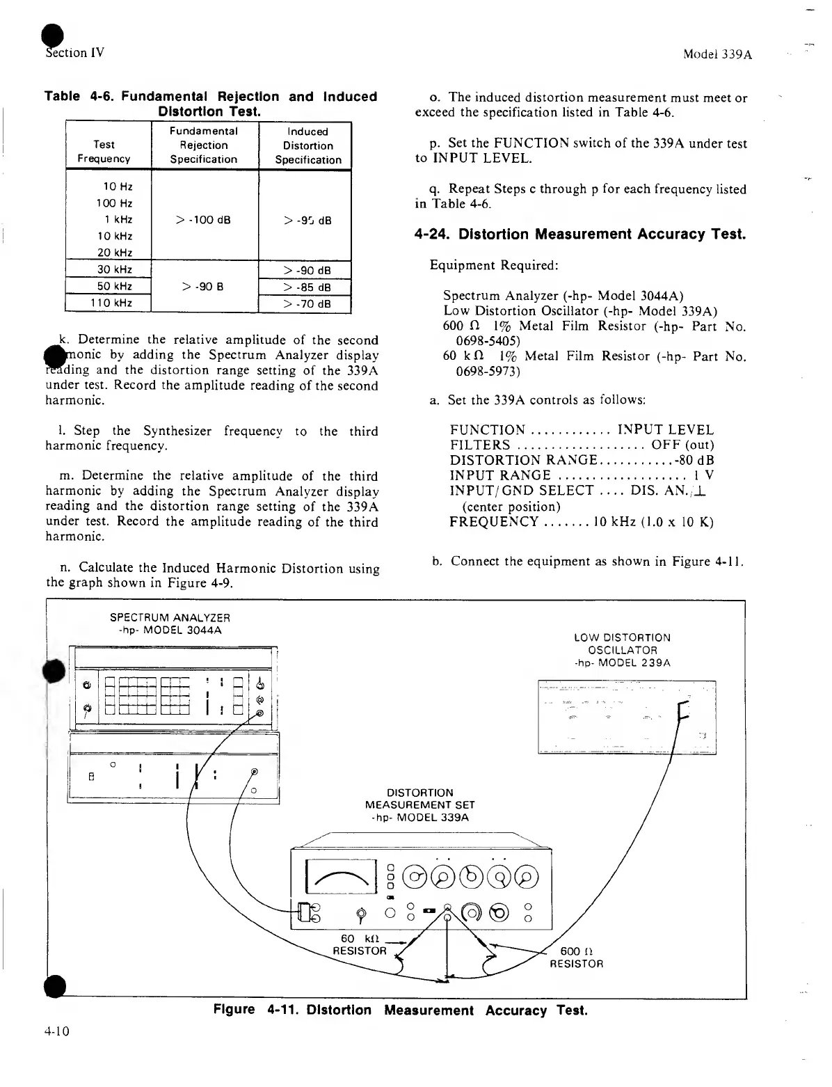
b
'
C° nnect the equipment as
shown
ln
Fi
S
ure
4
’>
>•
the
graph shown
in
Figure
4-9.
4-10
Figure 4-11.
Distortion
Measurement
Accuracy
Test.
 Loading...


