Model
339A
Section IV
Table
4-7.
Distortion Measurement
Accuracy Test.
Distortion
Frequency
Accuracy
Limits
10 Hz
+
1.0
dB,
-2.0
dB
20 Hz ±1.0 dB
100 Hz ±1.0 dB
20 kHz ±1.0 dB
50
kHz
+1.0
dB,
-2.0
dB
100 kHz + 1.5
dB,
-4.0
dB
330 kHz +1.5
dB,
-4.0
dB
c. Adjust the Synthesizer
(3330B) controls
for an
output frequency of
1
kHz
and
an
output
amplitude of
dBm.
d. Set the Low
Distortion Oscillator
for an output
frequency of
10 kHz. Adjust the output
level for
a
meter
indication
of 1
V
on the 339A under test.
e. Set
the FUNCTION switch
of the
339A
under test
to DISTORTION.
f. Adjust the Synthesizer
amplitude
as
necessary to
obtain a distortion reading
of
-80
dB
on the
339A
under
test (full-scale
meter indication).
g.
Set
the Spectrum Analyzer
(3571 A) to a
3 Hz
bandwidth, an
input
range of
+10
dB V,
an input
impedance of 1 M O
,
and
a
relative
display reference.
Reference the Spectrum Analyzer
to
the
339A
measurement
by
pressing the Enter Offset button.
h. Set
the Synthesizer
to each frequency
listed
in
Table
4-7, and verify
that the
Spectrum Analyzer reading is
within
the limits
listed.
4-25.
Residual Noise
Test.
Equipment
Required:
1 k
L2
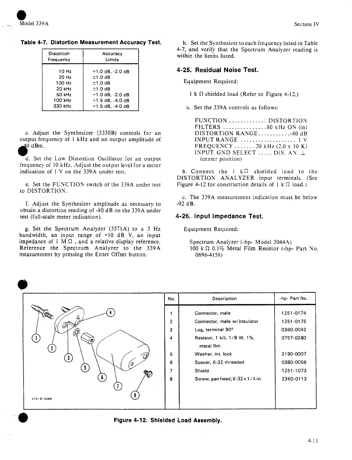
shielded
load (Refer
to Figure 4-12.)
a.
Set the 339A controls
as follows:
FUNCTION
DISTORTION
FILTERS
80 kHz ON (in)
DISTORTION
RANGE
-80
dB
INPUT
RANGE
IV
FREQUENCY
20 kHz
(2.0 x 10 K)
INPUT
GND SELECT
DIS.
AN.
_L
(center position)
b. Connect the 1
kL2
shielded load to the
DISTORTION ANALYZER input terminals. (See
Figure
4-12
for
construction
details of 1 k
L2
load.)
c. The
339A
measurement indication must be below
-92
dB.
4-26.
Input Impedance
Test.
Equipment Required:
Spectrum Analyzer (-hp-
Model
3044A)
100 k
£2
0.1%
Metal Film
Resistor (-hp-
Part No.
0698-4158)
No.
Description
-hp- Part
No.
Connector,
male 1251-0174
Connector,
male w/insulator 1251-0175
Lug,
terminal
90°
0360-0042
Resistor, 1 kH, 1/BW, 1
%,
0757-0280
metal flm
5
Washer, int. lock
2190-0007
6
Spacer,
6-32
threaded 0380-0058
7
Shield
1251-1073
8
Screw, pan head,
6-32
x 1 /4 in. 2360-0113
Figure
4-12.
Shielded
Load Assembly.
 Loading...


