Model 34SSA
Section VIII
TROUBLESHOOTING
B-174.
INTRODUCTION.
8-175.
The
following
ponions
of this manual contain
information to aid in
troubleshooting and repair
of
the
34S5A. This
information consists of a
General Block
Diagram Theory of Operation, a
Preliminary Trouble-
shooting Check, and eight
Service Croups. An instru-
ment block
diagram and schematics are also included in
this section of
the manual.
8-176.
Ganaral Bloch
Diagram
Theory
of Operation.
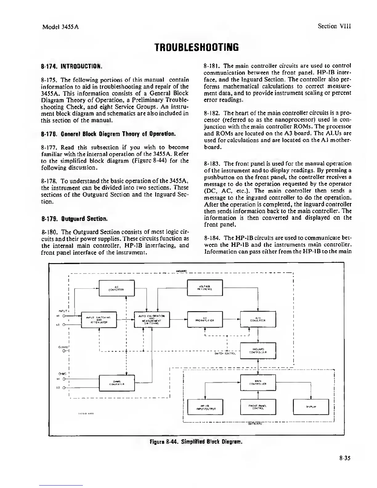
8-177.
Read this subsection if you
wish
to
become
familiar
with
the internal
operation of the 34S5A. Refer
to the
simplified block diagram
(Figure
8-44)
for
the
following discussion.
8-178.
To understand the
basic operation of the 345SA,
the instrument can be
divided into
two
sections. These
sections of the
Outguard Section and the Inguard Sec-
tion.
B-179.
Outguard Section.
8-180.
The
Outguard Section consists
of most logic cir-
cuits and
their
power
supplies. These
circuits function as
the internal
main controller, HP-IB
interfacing, and
front panel
interface of the instrument.
8-181.
The
main controller circuits are used to
control
communication between the front panel.
HP-IB inter-
face, and the
Inguard Section. The
controller also per-
forms
mathematical calculations to
correct measure-
ment data, and to
provide instrument scaling or percent
error readings.
8-182.
The heart of the main
controller circuits is a pro-
cessor (referred to as
the nanoprocessor) used in con-
junction
with
the
main controller ROMs. The processor
and ROMs are located on
the A3 board. The ALUs are
used for calculations and
are located on the A1 mother-
board.
8-183.
The front panel is used
for
the
manual operation
of the instrument and to
display readings. By pressing a
pushbutton on the
front panel, the controller
receives
a
message to do the
operation requested by the operator
(DC, AC, etc.).
The main controller then sends a
message to the inguard
controller to
do
the operation.
After the
operation is completed, the inguard controller
then
sends information back to the main
controller. The
information is then
converted and displayed on the
front
panel.
8-184.
The HP-IB circuits are used to
communicate bet-
ween the HP-IB and the
instruments main controller.
Information can pass either from
the HP-IB to the main
5r«EiK~
Figure B-44.
Simplified Block Diagram.
8-35
 Loading...


