EasyManua.ls Logo

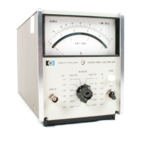
HP 3400A Service Manual

HP 3400A
81 pages
To Next Page IconTo Next Page
Page #1 background imageLoading...
Page #1 background image
A
biciano
Model
3400A
RMS
Voltmeter:

Other manuals for HP 3400A

Questions and Answers:

HP 3400A Specifications

General IconGeneral
BrandHP
Model3400A
CategoryMeasuring Instruments
LanguageEnglish

Summary

Manual Changes

Changes 1-4 (Serial Numbers & Errata)

Updates for serial ranges, schematic changes, and errata.

Warranty and Support Information

General Safety Precautions

Ground the Instrument

Minimize shock hazard by connecting chassis to electrical ground.

Avoid Hazardous Environments

Do not operate in flammable gas/fume presence.

Live Circuit Precautions

Do not remove covers; discharge circuits before touching.

Safety Symbol Definitions

Section I General Information

Section II Installation

Section III Operating Instructions

Controls and Indicators

Identifies and describes front panel controls and indicators.

Turn On Procedure

Steps to power on the instrument, including warm-up.

Operating Instruction

Basic steps for using the instrument as a voltmeter.

Operating Applications

Section IV Theory of Operation

General Description

Overview of the instrument's circuitry components.

Detailed Circuit Description (Part 1)

Detailed Circuit Description (Part 2)

Detailed Circuit Description (Part 3)

Detailed Circuit Description (Part 4)

Section V Maintenance

Introduction

Information for maintenance, checks, and calibration.

Test Equipment

Lists required test equipment for maintenance.

Performance Checks

In-cabinet tests to compare instrument to specifications.

Accuracy, Linearity, and DC Output Check

Test setup and procedure for checking accuracy.

Maintenance Checks (Part 1)

Maintenance Checks (Part 2)

Adjustment and Calibration Procedures

Adjustment and Calibration Procedures

Complete procedures for calibration and adjustment.

Mechanical Meter Zero

Procedure to mechanically zero the meter pointer.

Calibration and Power Supply Checks

Power Supply Checks

Checks power supply voltage and ripple tolerances.

Low Frequency Calibration

Calibration for low frequency response.

Amplifier Offset Adjustment

Adjustment for the amplifier offset.

Calibration Adjustments

High Frequency Calibration

High Frequency Calibration

Calibrates for optimum response at high frequencies.

Amplifier Gain Adjustment

Adjusts amplifier gain for 90% full scale reading.

Input Attenuator Adjustment

Adjusts input attenuator for frequency response.

Troubleshooting and Thermocouple Checks

Second Attenuator Adjustment

Adjusts the second attenuator.

Troubleshooting Procedures

Procedures for isolating malfunctions.

Checking Thermocouples TC401 and TC402

Procedure to check thermocouple operation.

Troubleshooting Symptoms and Thermocouple Tests

Troubleshooting Procedure Details

Thermocouple Replacement

Servicing Circuit Boards

Section VI Circuit Diagrams

Schematic Diagrams

Depicts circuits within each assembly and interconnections.

Parts Location Diagrams

Shows physical location of parts within assemblies.

Section VII Replaceable Parts

Introduction

Information for ordering replacement parts.

Ordering Information

How to address orders or inquiries for parts.

Non-Listed Parts

Information to include when ordering unlisted parts.

Parts Information

Appendix A Backdating

Appendix A Manual Changes

Appendix A Detailed Changes

Related product manuals