Section
VIII
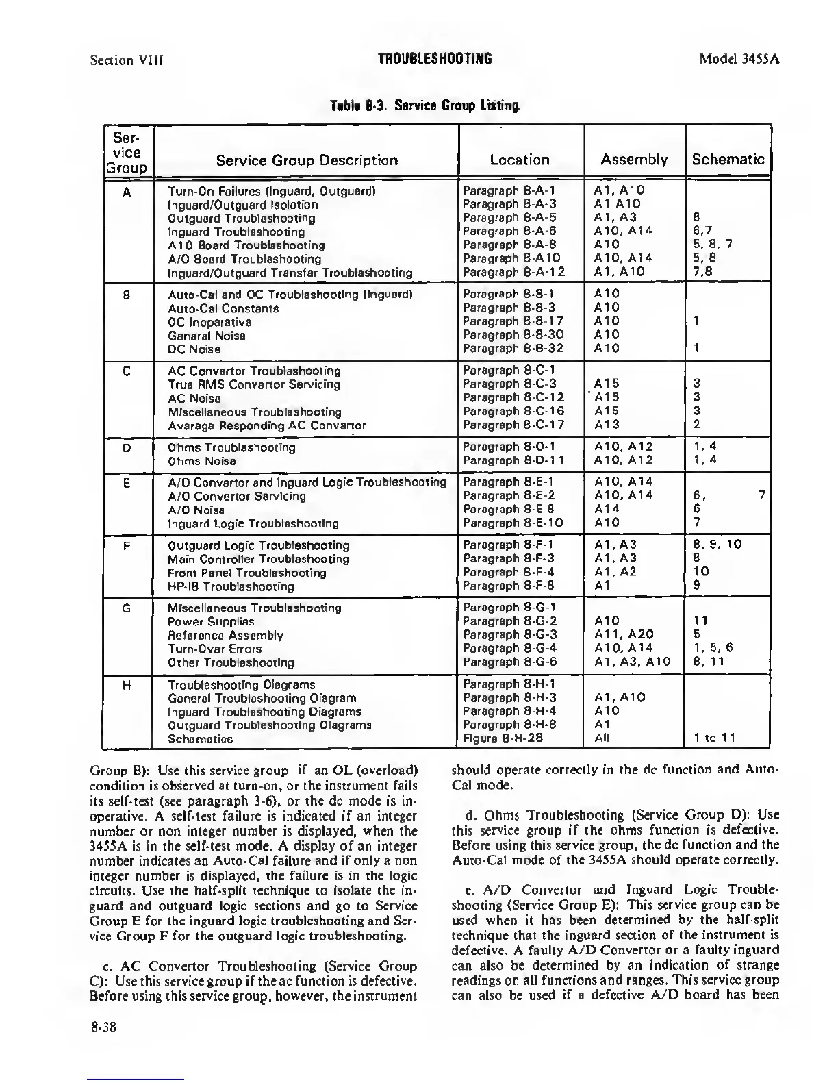
TROUBLESHOOTING Model 34S5A
Tfbl«
8-3.
Service Creep Listing.
Ser-
vice
Group
Service Group
Description
Location Assembly
Schematic
A Turn-On Failures
(Inguard. Outguard)
Paragraph 8-A-1 A1, AID
Inguard/Outguard Isolation
Outguard
Troubleshooting
Paragraph 8-A-3
Paragraph 8-A-5
A1 A10
A1, A3 a
lr>guard Troubleshooting
Paragraph 8-A-6 AID,
A14
6.7
A10
Board Troubleshooting
Paragraph
8-A-8 A10
5. 6.
7
A/0 Board
Troubleshooting
Paragraph 8-A10 A10, A14 6. 6
Inguard/Outguard Transfer
Troubleshooting
Paragraph 8-A-1
2
A1, A10 7.8
B
Auto-Cal and DC
Troubleshooting (Inguard) Paragraph 8-B-1
A10
Auto-Cal Constants
DC
Inoperative
Paragraph
8-B-3
Paragraph 8-B-1
7
AID
A10
1
General Noise
DC Noise
Paragraph 8-B-30
Paragraph 8-B-32
A10
AtO 1
C
AC Convertor
Troubleshooting
True RMS
Convertor Servicing
Paragraph
8-C-1
Paragraph 8-C-3 A15 3
AC Noise
Paragraph 8-C-12 A15 3
Miscellaneous
Troubleshooting
Paragraph 8-C-16 A16 3
Average Responding AC Convertor
Paragraph 8-C-1
7
A13 2
0 Ohms
Troubleshooting
Paragraph 8-D-1 AID.
A12 1,4
Ohms Noise
Paragraph
8-D-1
1
A10, A12 1,
4
E
A/D Convertor and
Inguard Logic Troubleshooting
Paragraph
8-E-1
AID, A14
A/D
Convertor Servicirig
Paragraph 8-E-2 A10, A14 6.
7
A/D
Noise
Paragraph 8-E-8 A14 6
Inguard Logic Troubleshooting
Paragraph 8-E-10
A10 7
F Outguard
Logic Troubleshooting
Paragraph 8-F-1 A1, A3 8. 9.
10
Main Controller Troubleshooting
Paragraph 8-F-3 A1. A3
8
Front Panel Troubleshooting
Paragraph
8-F-4
At. A2 10
HP-IB
Troubleshooting
Paragraph 8-F-8 A1 9
G
Miscellaneous Troubleshooting
Power Supplies
Paragraph
8-G-1
Paragraph 8-G-2
A10 1
1
Reference Assembly
Paragraph
8-G-3
A11, A20 5
Turn-Over
Errors
Paragraph
8-G-4
A10. A14
1,
5. 6
Other
Troubleshooting
Paragraph
8-G-6
A1. A3. A10
6,
11
H
Troubleshooting Diagrams
General Troubleshooting
Diagram
Inguard Troubleshooting Diagrams
Outguard
Troubleshooting Diagrams
Schematics
Paragraph 8-I-I-1
Paragraph 8-H-3
Paragraph 8-H-4
Paragraph
8-H-6
Figure 8-H-28
A1. A10
A10
A1
All 1 to 11
Group B): Use
this service group
if
an OL (overload)
condition is
observed at turn-on,
or
the instrument fails
its self-test (see
paragraph
3-6), or
the dc mode is in-
operative.
A
selMest failure is indicated if an integer
number
or non
integer number
is
displayed,
when
the
34S5A is in the self-test mode. A display of an
integer
number indicates an
Auto-Cal failure and if only a non
integer number
is
displayed, the failure is in the logic
circuits. Use the half-split technique to isolate the in-
guard and outguard logic sections and go to
Service
Group E for the inguard logic troubleshooting and Ser-
vice
Croup
F for the outguard logic troubleshooting.
c. AC
Convertor
Troubleshooting
(Service
Croup
C): Use
this service
group
if the ac function is defective.
Before using this service group,
however, the instrument
should
operate correctly in the dc
function and Auto-
Cal mode.
d.
Ohms Troubleshooting
(Service Group D): Use
this
service group if the ohms
function
is
defective.
Before using this
service group,
the dc
function and the
Auto-Cal
mode of
the 34SSA should operate correctly.
e. A/D
Convertor and Inguard Logic Trouble-
shooting
(Service
Group E):
This service group can be
used when it has been
determined by the half-split
technique that the inguard section
of the instrument is
defective.
A faulty
A/D Convertor or a faulty inguard
can also be
determined by an indication of strange
readings on all functions and ranges. This
service group
can also be used
if
a
defective A/D board has been
8-38
 Loading...


