Model 3455A
Section
VIII
SERVICE GROUP
B
8 B-1. AUTO-CAL AND
DC TROUBLESHOOTING
(INGUARD).
8-B-2.
All 3455A input
signals travel through the main dc
ampliner and Auto-Cal circuits. In
order
to
troubleshoot D.C. and Auto-Cal
malfunctions, a good fundamental
knowledge of the 3455A’s
Auto-Cal and self-test routines
are required.
B-B-3. Auto-Cal
Constants.
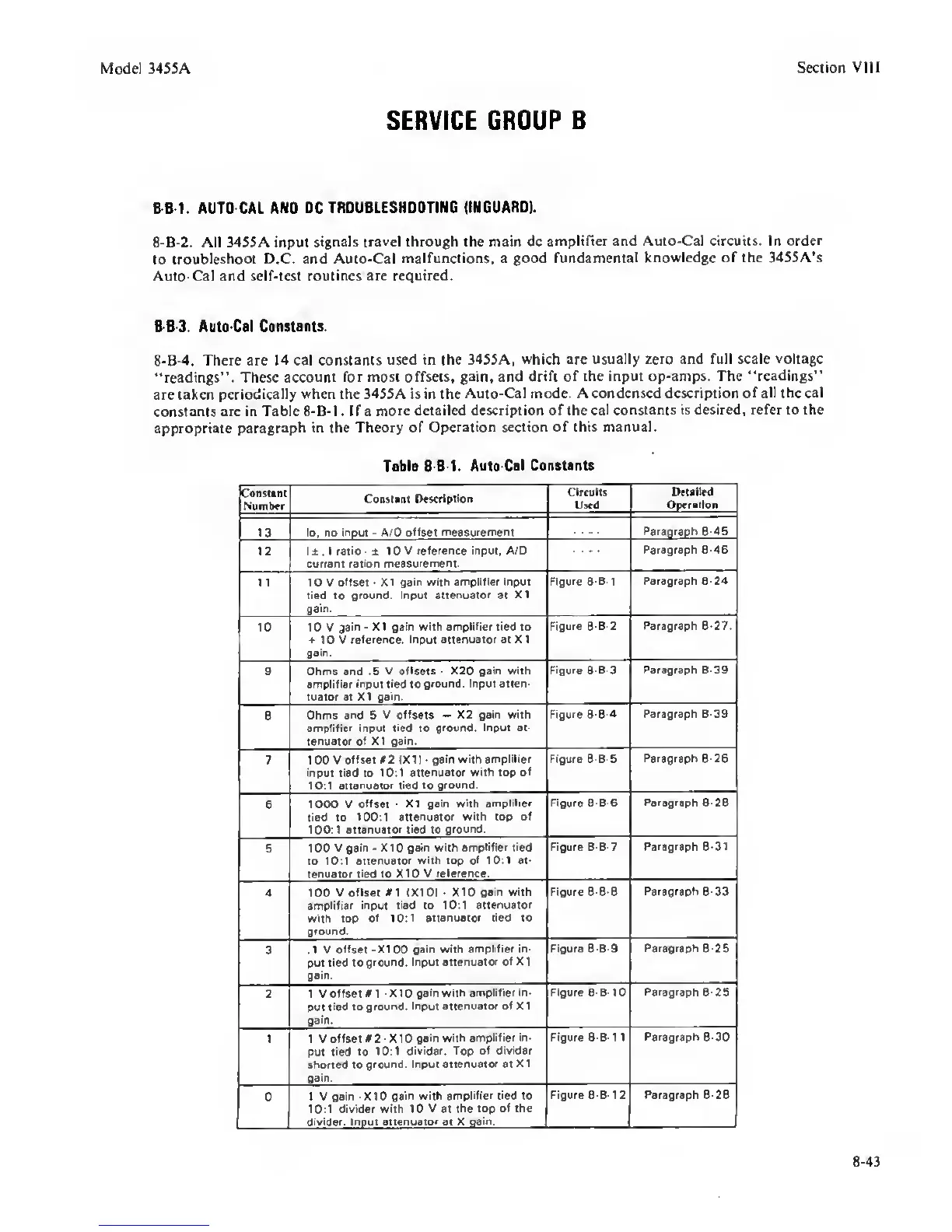
8-B-4.
There are
14
cal constants
used in the 34SSA,
which
are
usually zero and full scale
voltage
“readings”. These
account for most offsets, gain, and
drift of the input op-amps. The “readings”
are taken
periodically when the 3455A is in the
Auto-Cal mode. A condensed description
of all the cal
constants are in Table 8-B-I. If a
more detailed description of the
cal constants is desired, refer to the
appropriate
paragraph in the Theory of
Operation section of this manual.
Table 8-B-I.
Aute-Cal Constants
Coutul
N'aoibtr
CoBsiani
Oncriplioo
Circa its
Used
Detailed
Ooeration
13 lo. no Inout
-
A/D
oHsei measurement
Fsrsoraoh 8-4S
12 l±.lratio-± 10 V
reference input, A/D
current
ration measurement.
—
Paragraph
8-46
1
1
10 V
offset
-
XI gain with amplifier input
tied
to
grourtd. Input
attenuator
at
XI
asm.
Figure 8-B-I Paragraph
8-24
10 10 V
jain
-
XI gain with
amplifier
tied to
10 V
reference. Input attenuator at XI
gain.
Figure
6-8-2
Paragraph
8-27.
9
Ohms and .5 V
offsets
-
X20 gain with
amplllier
input tied
to
grourtd. Input anen-
tuator at XI
gain.
Figure
8-B-3
Paragraph
8-39
8
Ohms
and
5 V
offsets
—
X2 gain with
amplifier input
tied
to
ground. Input et-
tenuator of XI gain.
Figure
8-B-4
Paragraph
8-39
7 100 V
offset #2 (XI) -
gain with amplifier
input tied to 10:1
attenuator with top
of
10:1
attenuator tied
to
ground.
Figure 8-B-5
Paragraph
8-26
6
1000 V
Offset
-
X1 gain
with amplifier
tied to 100:1
attenuator with top of
100:1
attenuator tied
to
ground.
Figure B-B-6
Paragraph 8-26
5 1 00 V
gain
•
X
1
0
gain with
amplifier tied
to 10:1
attenuator with top of 10:1 at-
tenuator
tied
to X10 V
reference.
Figure B-B-7
Paragraph
8-31
4 100
V offset ei 1X10)
•
X10
gain with
amplifier input tied to 10:1
attenuator
with
top
of 10:1 attenuator tied to
ground.
Figure 8-B-8
Paragraph 8-33
3
.1 V
offset -X100 gain with
amplifier in-
put tied to
ground. Input attenuator
of
X
1
gain.
Figure 8 B 9
Paragraph
8 26
2
1
Voffsetfl -X10 gain with
amplifier in-
put
tied to ground.
Input attenuator of XI
gam.
Figure 8-B-IO
Paragraph 8-25
1 1 V
offset «2
-X
10
gain with
amplifier in-
put
tied to 10:1
divider. Top of divider
shorted to
ground. Input
attenuator
at
XI
gam.
Figure 8-B-1
1
Paragraph 8-30
0
1 V gain -X10
gain with amplifier tied to
10:1 divider
with
10 V at
the top of the
divirfer. Inout
attenuator
at X
gain.
Figure 8-B-I
2
Paragraph
8-28
8-43
 Loading...


