Model 3455A
SERVICE GROUP
C
Section VIII
8 C l. AC
CONVERTOR TROUBLESHOOTING.
8-C-2. True RMS Convtrtor Sarvieing (Schamatic
3).
8-C-3. Before troubleshooting the 345SA's True RMS Convertor, the instrument should operate
properly in the dc mode. Verify for the correct operation of the dc section, before
servicing
the ac
convertor.
The
following
procedure should be
followed
before troubleshooting or repairing the ac
convertor.
a.
Check the
dc
operation of
the 3455A.
Verify
for correct full scale and zero scale
readings on
all
ranges.
b. Set the 34SSA to the 10
V
range, ac function, and short the input.
c.
Check for approximate zero
levels
at A1STP8 and TPS,
with
the
low
input of the meter con-
nected to TP6 (go to paragraph 8-C-4 or 8-C-6 if bad).
d. Short
TP3 to TP6 and measure the
voltage
at
TPI. TPl should read approximately
zero.
Remove the short
(go to
paragraph
8-C-8
if bad).
e. Check for proper biasing of A1SU2. The
voltage
at U2 pin 2
should
be
between
-2
mV
and
-3
mV. Repad R2I if necessary (R2I padding list
is
in the parts
list).
f.
Remove
the short form the input of the 34SSA. Apply a 10
V,
100 Hz
sinewave
at the input ter-
minals. Check for the
following voltages.
1. With
an oscilloscope, check for a
sinewave
at A15TP8. The amplitude of the
sinewave
should
be
approximately 2.8 V peak
to
peak with no
shift in the dc
level
(go to
paragraph
8-C-4
if bad).
2. A halfwave rectified sinewave should
be
observed
at
TPS. The
amplitude of the
waveshape
should be approximately 1.4 V peak to peak,
with
no shift in the dc level
(go
to
paragraph 8-C-6 if bad).
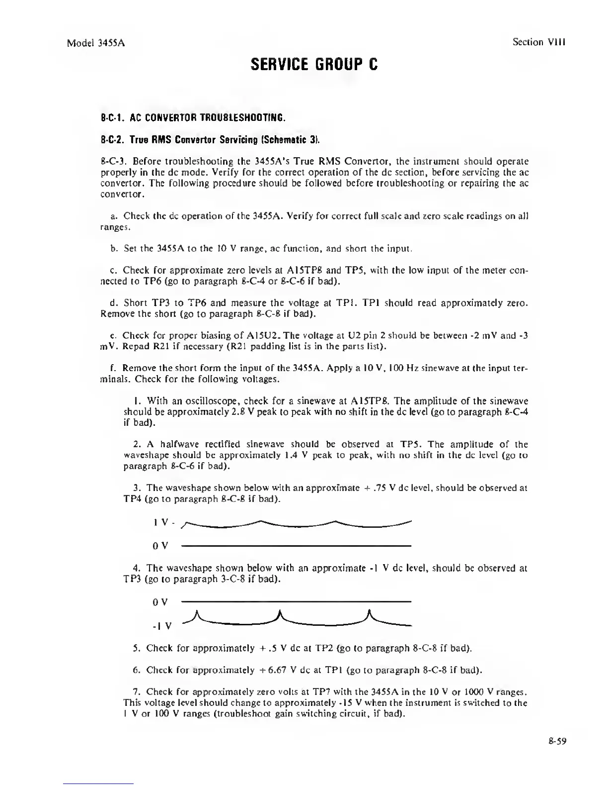
3. The
waveshape shown
below
with
an approximate + .7S
V
dc level, should be observed
at
TP4 (go to paragraph 8-C-8 if bad).
0
V
4. The
waveshape shown below with
an approximate
-1
V
dc
level,
should be observed at
TP3 (go to
paragraph
3-C-8 if bad).
0 V
5. Check for approximately
-f
.S
V
dc at
TP2
(go to paragraph 8-C-8 if bad).
6.
Check
for approximately +6.67 V
dc
at TPl
(go to
paragraph
8-C-8 if bad).
7. Check for approximately zero
volts
at TP7
with
the 34SSA in the 10 V
or
1000 V ranges.
This
voltage level
should change to approximately -IS
V when
the instrument is switched
to
the
1 V or 100 V ranges (troubleshoot gain switching
circuit, if bad).
8-S9
 Loading...


