Model 3455A SERVICE
GROUP
E Section
Vlll
f. For no A/D waveform at TPl, go to paragraph 8-E-4 for troubleshooting.
For an incorrect
waveform
go to paragraph 8-E-6.
8 E4. No A/D Wavoform.
8-E-S. Since the A/D
waveform
is dependent on various circuits
in
the 3455
A (input,
main amplifier,
etc.), isolation of these circuits is necessary. The method used
is
simply
a
signal tracing method with
limited operational checks.
a. Set up the 3455A using the procedure of paragraph
8-E'3a, b,
and
c.
b. Measure the
voltage
at the multiplex node (sources of AlOQI,
Q2, Q3,
and
Q4).
If the voltage
is
not
-10 V
dc, the input circuit may be inoperative. The multiplex node may also be loaded down
by
one or more FETs.
c. Measure for a
>10 V
dc
voltage
at A10TP4. If the
voltage
is incorrect, troubleshoot the main
amplifier
circuit. Make sure A10Q19
is turned on.
d. Measure the instrument's reference
voltages.
A10TP8 should be
-f
10
V
± 100 and TP7
should be
•
10
V
± 20
mV.
If the reference
voltages
are incorrect, troubleshoot the reference assembly
(A 1 1 or A20)
and/or
U7. The reference
voltages are
used on the A/D
board
and should be correct for
proper A/D operation.
e.
Short across capacitor A14C2 and measure the voltage at A14TP1. The voltage should
be
ap-
proximately zero. If there are any great offsets, troubleshoot A14U3 and associated circuits. If the
voltage
at TPl is good,
remove
the short from C2 and continue
with
this procedure.
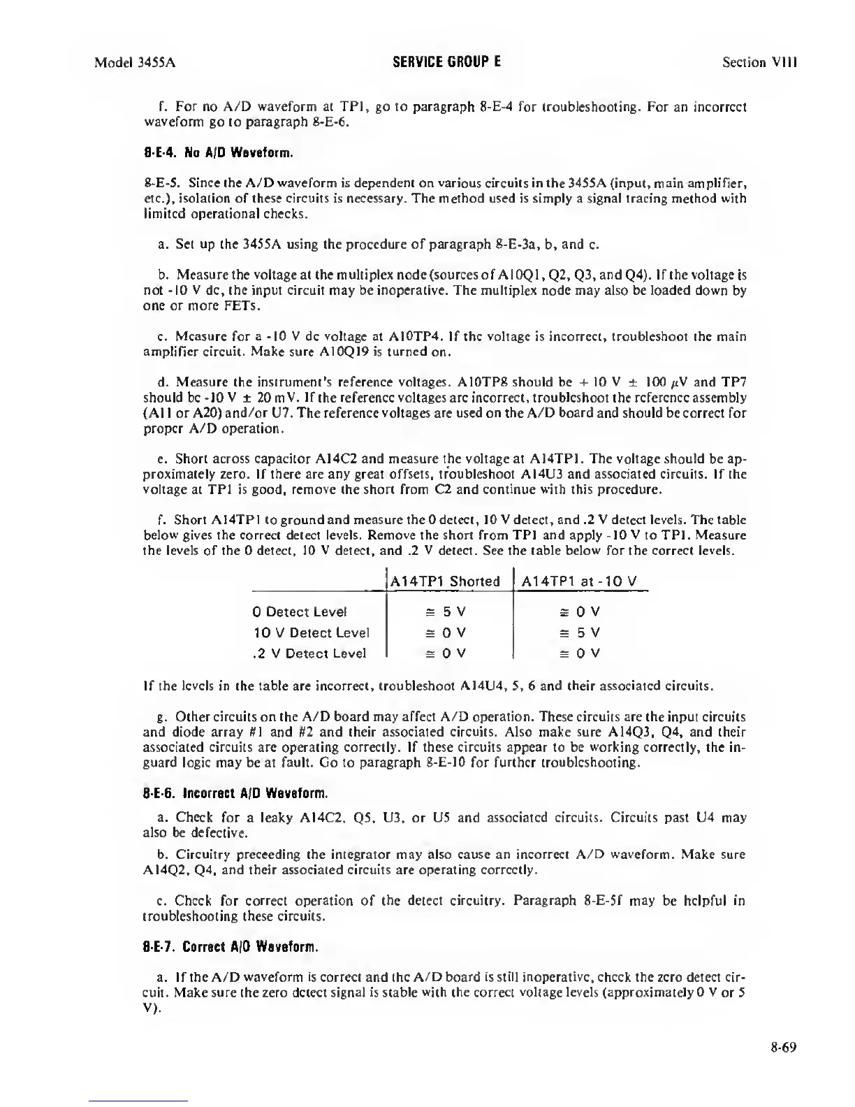
f.
Short AI4TP1 to ground and measure the 0 detect, 10 V detect, and .2 V detect levels.
The
table
below gives the correct detect levels.
Remove
the short from TPl and apply
-10
V to TPl. Measure
the levels of the 0 detect, 10
V
detect, and .2
V
detect. See the table
below
for the correct levels.
A14TP1 Shorted
A14TP1
at
-10
V
0
Detect Level s
5
V s
0
V
1 0 V
Detect Level s
0 V
s
5
V
.2 V Detect
Level s
0 V
s
0 V
If the
levels
in the table are incorrect, troubleshoot A14U4,
5,
6 and their associated circuits.
g.
Other circuits
on the A/D board may
affect A/D operation.
These
circuits are the
input circuits
and diode array U\ and #2 and their associated circuits. Also make sure A14Q3,
Q4,
and
their
associated circuits are operating correctly. If these circuits appear to be
working
correctly, the in-
guard logic may be at fault. Go to paragraph
8-E-lO
for further
troubleshooting.
8-E-6. Incorrect A/D Waveform.
a. Check
for a leaky AI4C2,
Q5,
U3,
or U5 and associated circuits. Circuits past U4 may
also be defective.
b. Circuitry preceeding the integrator may also cause an incorrect A/D
waveform.
Make sure
A14Q2,
Q4,
and their associated circuits are operating correctly.
c. Check for correct
operation
of the
detect circuitry. Paragraph 8-E-5f
may be helpful in
troubleshooting these circuits.
B
E-7. Correct A/D Waveform.
a. If the A/D
waveform
is correct and the
A/D
board is still
inoperative,
check the zero detect cir-
cuit. Make sure the zero detect signal
is stable with
the correct
voltage levels (approximately
0
V
or 5
V).
8-69
 Loading...


