Model
3455A
Section VIII
SERVICE GROUP F
8 F-1. OUTGUARD LOGIC
TROUBLESKOOTING (SCHEMATIC 8. 9. 10).
8-F-2.
Outguard logic troubleshooting
should be done using the Signature
Analysis Routines (SA) in
Figures
8-H-20 to 8-H-27. If any
incorrect signatures are
observed, the following checks may be
helpful.
a. If any incorrect signatures
are observed check
for
a
I ^F capacitor across AIU49. Install one
if
missing (part
number
0180-0291).
The
capacitor should be installed to the
underside of the A1
motherboard, with the + terminal to pin
14 of
U49
and the
•
terminal
to
pin 7
of
U49.
b.
If no stable signature can be located
and the A3 board has
been replaced, check the IC signals.
Make sure they are
toggling with good logic highs and
lows (approximately 4
V
peak to
peak).
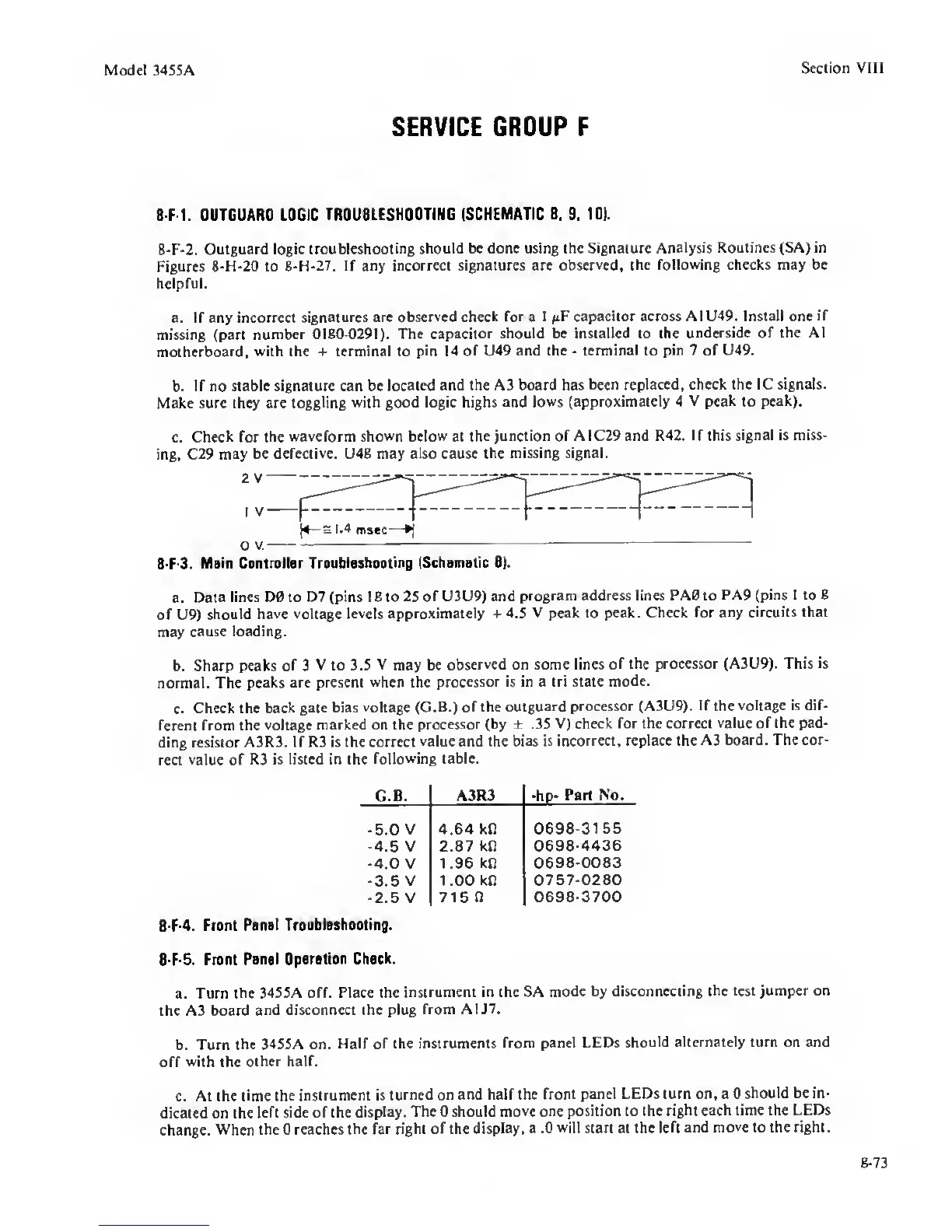
c.
Check for
the waveform
shown below
at the
junction of A1C29 and R42. If this
signal
is
miss-
ing, C29 may
be defective. U48 may also cause
the missing signal.
2
V
I V
(4—3 1.4
msec-
O
V.
8 F-3.
Main Controller
Troubleshooting (Schematic 8).
a. Data
lines D0 to D7 (pins 1 8 to 25
of U3U9) and
program address lines PA0 to
PA9 (pins 1
to
8
of U9)
should have
voltage levels approximately +
4.5 V peak to peak. Check for
any circuits that
may
cause loading.
b. Sharp peaks
of
3
V to 3.5
V
may be
observed on some lines of
the processor (A3U9). This is
normal. The peaks
are present
when
the
processor is in a tri state
mode.
c.
Check the
back gate bias
voltage (G.B.) of the outguard
processor (A3U9).
If
the
voltage is dif-
ferent
from the
voltage marked on the
processor (by ± .35
V) check for the correct
value
of
the pad-
ding resistor
A3R3. If R3 is the correct
value and the bias is
incorrect, replace the A3
board. The cor-
rect
value
of
R3 is listed in the
following table.
G.B. A3R3 •hp-
Part No.
•5.0 V 4.64 kO
0698-3155
-4.5
V
2.87 kn
0698-4436
-4.0
V
1.96
kR
0698-0083
-3.5
V
1 .00 kO
0757-0280
•2.5
V
715
n
0698-3700
8 F-4.
Front
Ponol Troubleshoot ng.
8-F-5.
Front
Panel Oporotion
Check.
a. Turn the
3455A off. Place the
instrument in the SA
mode by disconnecting the
test jumper on
the A3 board
and disconnect the plug
from A1J7.
b. Turn
the 3455A on.
Half
of
the instruments
from panel LEDs
should alternately turn on and
off
with
the
other half.
c.
At the time the
instrument is turned
on and half the front
panel LEDs turn on, a 0
should be in-
dicated on the
left side of the display.
The 0 should
move one position to the
right each time the LEDs
change.
When the 0 reaches the far
right of the
display, a .0
will
start at the
left and move to the right.
8-73
 Loading...


