With
A
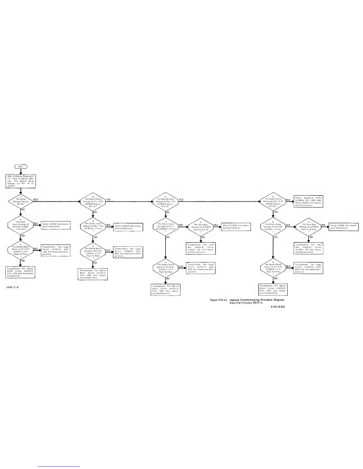
Display Reading Of
•4''
(Test 4 Failure), Mea-
sure The Switch Drive
Voltage On
Pin
14 Of
A10U4.
Check A10U9
And
Assoc-
iated
Components.
Check
A10U5
And
Associ-
ated Components.
Troubleshoot The
Gate
Troubleshoot The
Gate
Bias Amplitier Circuit Bias Ampliliei Cucuit
(A10U1.
OB
And
Associ- (A10U1,
QB
And Associ-
ated
Components). ated Components).
1
'
V
Troubleshoot
The Logic
^XThe
Device Seleci\,^
Troubleshoot The Logic
Circuit
(A10U13. U22.
^^Signa^t Pi
n
9
Of
^ES
^ Circuit
(A10U16.
U22,
U2€
And
Associated Com- 1 A10U16>4V
•
U26
And Associated Com-
poncnts). ^sPeak-To-Peak/'''^ ponents).
3455-D-a
Troubleshoot
The Device
Select Circuit
<A10U13.
U14. U2€
And Associ-
ated
Components).
NO
Troubleshoot The Device
Select Circuit (A10U16.
U14. U26
And Associ-
I
aied Components).
Figure 8-H-I2. inguard
Troubleshooting Procedure Diagram,
Auto-Cal Circuitry TEST 4.
8
-
101 /
8-102