NOTE
;
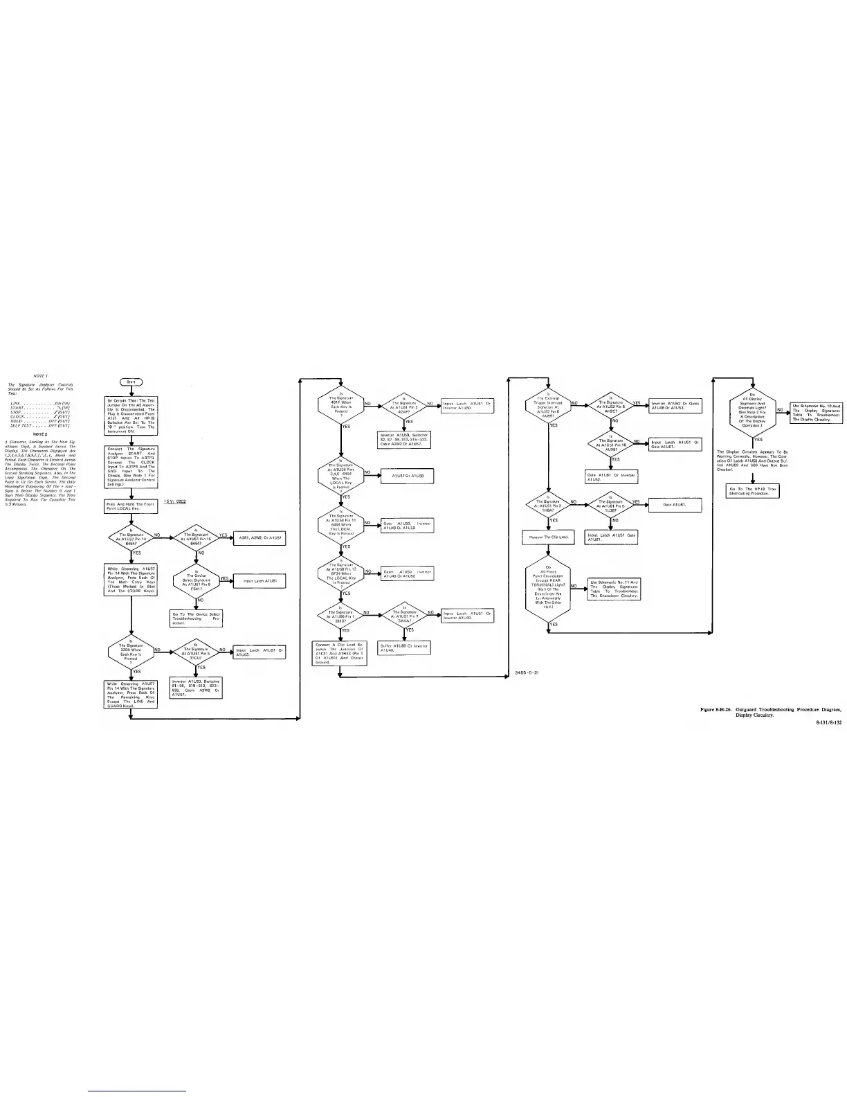
The
Signature Analyzer Controls
Should Be Set As
Follows
For This
Test!
LINE ON (IN)
START \-(lN)
STOP J‘(OUT)
CLOCK y(OUT)
HOLD OFF(OUT)
SELFTEST OFF(OUT)
NOTE
2
A
Character, Starting At The Most Sig-
nificant
Digit,
Is
Strobed Across The
Display. The Characters Displayed Are
l.2,3.4.5.6.7.8,9.l,l.".r,L, Blank And
Period. Each Character Is Strobed Across
The Display Twice.
The Decimal
Point
Accompanies The Character On The
Second
Strobing Sequence. Also, In
The
Least Significant Digit, The Decimal
Point
Is
Lit On Each Strobe. The Only
Meaningful Displaying Of The
+
And
Signs Is
Before The Number
0 And 1
Start Their Display Sequence. The Time
Required To Run The Complete Test
Is 3 Minutes.
(
Si^
^
Be Certain That; The Test
Jumper On The A3 Assem-
bly
Is
Disconnected,
The
Plug Is Disconnected Prom
A1J7
And All HP-IB
Switches Are Set To The
"0 "
position. Turn
The
Instrument ON.
I
Connect The Signature
Analyzer START Artd
STOP Inputs To A3TP3.
Connect
The
CLOCK
Input To A3TP5 And The
GND
Input
To
The
Chassis. (See Note 1
For
Signature
Analyzer Control
Settings.)
I. W
1
Press And Hold The Front
Panel LOCAL Key.
•tev:
02C2 The
Signature^^
N. NO
1
^
The Signature"^
'^YES
.
ls^\.
*\At A1U61 Pin
2
1H8A?
At A1U61 Pin
5
1U38?
Gate AtUdI.
The Signature
^
1
330H
When
INO
The Signature
^
NO
1
Input Latch
A1U51 Or
1
Each Key Is
'“n.
Pressed
•Sw
At A1U51
Pin
6
31CU?
^
*
A1U53.
While Observing
A1U57
Pin 14 With
The Signature
Analyzer, Press Each
Of
The
Remaining Keys
Except The LINE And
GUARD Keys).
rvEs
Inverter
A1U53,
Switches
S1-S6, S10-S13, S23-
S28,
Cable A2W2
Or
A1U57.
I
The Signature
1
401
F
When
NO
»
/ Is
The
Signature
^
s. NO
^
Input
Latch
A1U51
Or
The External \
1
Trigger Interrupt
^NO
>
The Signature
^
s^ES
^
Inverter A1U52 Or Gates
1 Each Key Is
k. Pressed
At
A1U51 Pin 2
42AP?
Inverter
A1 U50.
1 Signature At
\
A1U52Pin6
^
•C At A1U52 Pin 5
AH2C?
A1U46 Or A1U53.
lYES
lYES
Inverter A1U50,
Switches
S2, S7
-S9, S13, S15-S22,
Cable A2W2
Or
A1U57.
The Signature
At
A1U58
Pins
3,4,6
6464
When
The
LOCAL
Key
Is
Pressed
?
NO
The Signature
AtA1U58Pin1I Y
6464 When fc
Gate A1US0,
Inverter
The LOCAL
J
Kev Is
Pressed
^
A1 U49 Or AIUSS
fYES
f
At
A1U58
Pin 13
Ino
^ Gates
A1U50
Inverter
6F34Wher\
L
The LOCAL Key
.
A1 U49 Or A1U58
Is Pressed
7
^
The
Signature
^
N.
NO
/
*
\
The Signature
^
V.
NO
^
Input Latch A1U51 Or
Troubleshooting Pro-
cedure.
At A1U60
Pin 1
3818?
At A1U51
Pin
7
3AAA?
^
9
Inverter A1
U49.
Connect A Clip Lead Be-
tween The Junction Of
A1C41
And
A1R43
(Pin 1
Of A1U61I And Chassis
Ground.
Buffer
A1U60 Or Inverter
A1U49.
I
Do
All Display
Segments And
Decimals Light?
(See Note
2
For
A Description
Of
The
Display
Operation.)
[YES
Use Schematic
No. 10 And
The
Display
Signatures
Table
To Troubleshoot
The Display
Circuitry.
The Display Circuitry
Appears To Be
Working Correctly, However,
The Oper-
ation
Of
Latch A1
US8
And Output
Buf-
fers A1U59 And
U60 Have Not Been
Checked.
i
Go To The HP-IB Trou-
bleshooting Procedure,
Figure 8-H-26. Outguard Troubleshooting Procedure Diagram,
Display Circuitry.
8-131/8-132
 Loading...


