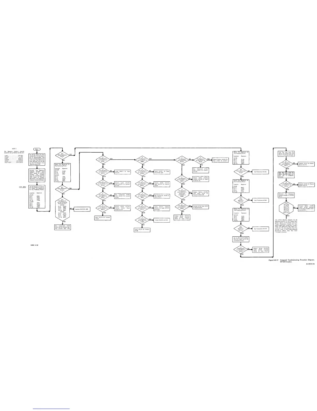
NOTE 1
The Signature
Analyzer controls
should be set
as
follows for this test;
LINE
ON (IN)
START.
(IN)
STOP y(OUT)
CLOCK.
y(OUT)
HOLD
OFF(OUT)
SELF TEST OFF
(OUT)
+
5V:
79FU
^
St^
Be
Certain That: The Test
Jumper On The A3
Assem-
bly is
Disconnected, The
Plug Is Disconnected
Prom
A1J7 And
The HP-IB Ad-
dress
Switches Are All Set
To
The
"0"
Position.
Turn
The Instrument
ON.
I
Connect The
Signature
Analyzer START And
STOP Inputs To
A3TP4.
Connect The CLOCK
Input To A3TP5 And The
GNO Input To Chassis,
(See Note t
For Signature
Analyzer Control Settings.l
I
1
Use the Signature Analyzer
1
To
Check The Signatures
At The Following Points:
Location
Signature
A1U34
Pin 2
6P03
Pins
40CF
Pin 9
2A3P
Pin 12
77H9
A1U42
Pin
2
6P52
Pin
S
0A1A
Pin 9
A726
Pin 12
6725
I
Check
The Signatures At I
The Foilowing Points: I
Location Signature
A1U18
Pin
1 CH2H
Pin
9
91PF
Pin 12 2952
A1U17
Pin 1 1P03
Pin
4 HC7A
Pin
9
1018
Pin 12
390F
Are
The Signatures
At
The Following
Points Correct?
A1U19
Pin
2 CH2H
Pin 5 2952
Pin
7
91PF
Pin 10 390
F
A1U20
Pin
2
1018
Pin
5
HC7A
Pin 7 1P03
Pin 10 28PH
f^S
Latch
A1U11 Or Gate
A1U14.
Output Letch A1U16,
yft'
The Signature
^
SJTES
^
Output Suffer A1U16.
Gate AIU14, Or Inverter
\
At A1U14
Pin
1 Gate A1U14 Or Inverter
A1U10.
\qOF8?
A1U8.
Bus Transceiver
A1U9,
Gate A1U13 Or Inverter
A1U8.
Output Suffer A1U15,
Inverter AIU3, Gates
A1U2 0r U14.
But
Transceivers
A1U6
1
And U12
Or Output 6uf-
fers A1U17 And U18.
1
Output Buffer AIU15 Or
Gate A1U7 Or A1U13.
Bus Transceiver A1U9,
Gate A1U13
Or Inverter
A1U10.
Output Buffer A1U15,
Inverter A1U10
Or Gates
A1U2 Or U7.
^
The Signature
At
A1U15 Pins 1
K
Output Buffers A1 U1
5,
And
5
And
U18 Letch A1U4
Or
L A1U18Pin5
00007 ^
Inverters A1 U3, U8.
Inverter
A1U1
Gate
A1LI7
Or
Switch
A1S1.
Output Buffer A1U16,
Letch A1U4,
Inverter
A1U3
Or Gate A1U7.
I
1
Check The
Signatures
At I
The Followir>g Points: 1
Location Signature
A1U9
Pin 2 27UU
Pin
7
OOFS
Pin
9
P6U5
Pin
15
709H
Check
The
Signatures
At
1
The Following Points;
Locat ion Signature
;
A1U6
Pin2 69H7
Pin
7 A2C5
Pin
9
67FF
Pin IS 5122
Yyes
These
^
\N0
J
Signatures
Bus
Transceiver A1U6.
^^Coffect?/
lYES
I
Check The Signatures At
The Following Points:
Location Signature
I
A1U12
Pin 2
F4P2
Pin
7
509H
Pin
9
P823
Pin 15 40F3
These
^
Latch
A1U11
Or Inverter
A1U8.
Signatures
Correct?
^
Bus
Transceiver A1U12
lYES
Use
A
Clip Lead To
Short
The IFC Input IJ3
Pin
9)
To
Chassis Ground.
3455
-
0-22
Output Buffer A1U16,
Latch A1U4,
Inverter
A1U3,
Or Gate A1U7.
1
Use
The Clip Lead To
Short The ATN Input (J3
Pin 111 To
Chassis Ground.
Inverter A1U3
Or Output
Buffer A1U16.
Use The Clip Lead
To
Short The
REN Input
U2
Pin
16)
To Chassis
Ground.
Inverter A1U3 Or Output
Buffer
A1U15.
Connect
The Signature
Analyzer Probe
To
A1U16
Pin 5.
Does
The
Probe
Tip Blink
When The
Ground
Is
Removed
From
The
^REN
Inpu^
f^S
The
HP-IB Circuitry
Appears
To Be
Working Correctly. If The Problem Still
Exists: Check To
Be Certain
That
The
Proper Procedures linguard Or Out-
guard) Have
Been Performed.
Trouble-
shoot
The ROM And Page Select Cir-
cuitry On
The
A3
Assembly And
The
Circuits Listed In The Troubleshooting
Procedures Which Have Not
Been
Thoroughly Checked.
Output Suffer A1U1B,
Latch A1U4,
Inverters
A1U3
And
AlUBOr
A1C1
And A1R11.
Figure 8-H-27
Outguard
Troubleshooting
Procedure Diagram.
HP-IB
Circuitry.
8-133/8-134
 Loading...


