Section IV Model .1455A
4-41.
The DC Transfer Standard required for the
following test must be calibrated to a 1. 017
V
to
1.019 V
standard cell that has been calibrated by the
National
Bureau of Standards
(NBS). If
the 3435A is to be
tested
for its 24-hour accuracy
specifications, the Transfer
Standard must be
adjusted
for
optimum 1-volt and
10-volt output accuracy using NBS-calibrated stan-
dards. It is recommended that the Transfer Standard be
calibrated
and adjusted just prior to use. After calibra-
tion, it should be left on and. if possible, kept in a con-
trolled environment
where
the ambient temperature is
within one or two degrees of the temperature in
which
it
was calibrated. The
following
procedure should be per-
formed in that same
environment.
4-42.
If the recommended DC Transfer Standard
or its
equivalent
is not available, an NBS-calibrated standard
cell (1.017 V
to
1.019 V)
can be substituted. If this is
done, check the full-scale accuracy of
the 34S5A 1
V and
10
V
ranges using the Reference Divider recommended
in the procedue.
443.
Test Proeadurt.
Equipment Required:
Reference
Divider
(Fluke Model 7S0A)
DC
Transfer
Standard (Fluke Model 731A)
DC Standard (Systron
Donner
Model M106A)
DC Null Voltmeter
(-hp-
Model
419A)
a. Set the
34S5A
controls
as
follows:
FUNCTION DCV
RANGE 1 V
HIGH RESOLUTION OFF
AUTO CAL ON
GUARD ON
TRIGGER INTERNAL
b. Set the DC Transfer Standard for an output of I
V. Connect the output of the transfer standard
to
the
3455A INPUT.
c.
The 3455A reading should
be
within
the test limits
listed
in
Table 4-9, verifying
its
1-volt
full-scale accuracy
with High Resolution off.
Tabla
4-8.
DC Accaracy Test (1 V, 10 V Fall-Seala; High
Ratolutian
Off).
Input 34SSA 24 Hour
90 Oey
Level Renge Test Limits Limits
1
V
1
V
0.99996 to 1.00004 0.99993 to 1.00007
10 V 10 V 9.9997
to
10.0003 9.9994
to 10.0006
d. Set the 3455A HIGH RESOLUTION to ON. The
345SA reading should
be
within
the test limits listed in
Table 4-10, verifying
its
1-volt
full scale accuracy
with
High Resolution on.
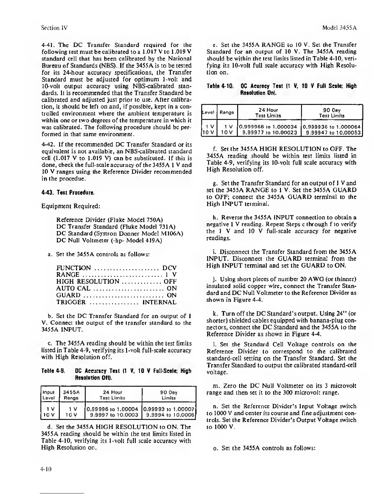
e. Set the 3455A RANGE to
10 V. Set
the
Transfer
Standard for
an output
of
10 V. The 345SA reading
should
be
within the
test
limits listed in Table 4-10, veri-
fying its 10-volt full scale accuracy
with
High
Resolu-
tion on.
Table 410.
DC
Aearaey Teat
(1 V.
10 V Full Stale; High
Retalulian On).
.evel Renge
24 Hour
Test Limits
90 Dsy
Test Limits
1 V
10 V
1 V
lOV
0.999966
to
1.000034
9.99977 to 10.00023
0.999936
to 1.000064
9.99947
to 10.00063
f. Set the 3455A HIGH RESOLUTION to OFF. The
34SSA reading
should
be
within
test
limits listed in
Table 4-9, verifying
its
10-volt full scale accuracy with
High Resolution off.
g.
Set the Transfer Standard for an output of 1
V
and
set the 3455A RANGE to 1
V.
Set the 3455A
GUARD
to OFF; connect the 34SSA
GUARD terminal
to
the
High INPUT terminal.
h.
Reverse
the 34SSA INPUT connection to obtain a
negative
1
V reading.
Repeat
Steps
c
through f
to
verify
the
I V and 10 V full-scale accuracy for negative
readings.
i. Disconnect the Transfer Standard from the 345SA
INPUT. Disconnect the GUARD terminal from the
High INPUT terminal and set the
GUARD
to
ON.
j.
Using short pieces of number 20 AWG (or thinner)
insulated solid copper
wire,
connect the Transfer Stan-
dard and DC Null
Voltmeter
to the Reference
Divider
as
shown
in Figure
44.
k. Turn
off
the DC
Standard’s output. Using
24”
(or
shorter) shielded cables equipped with banana-plug con-
nectors, connect the DC Standard and the 34S5A to the
Reference
Divider
as
shown
in Figure
44.
l.
Set
the Standard Cell Voltage controls on the
Reference Divider
to
correspond to the calibrated
standard-cell setting
on
the Transfer Standard. Set the
Transfer Standard to output
the calibrated standard-cell
voltage.
m. Zero the DC Null Voltmeter on its 3
microvolt
range and then set it to the 300
microvolt range.
n. Set the Reference Divider’s Input Voltage switch
to 10(X) V and center its course and fine adjustment con-
trols. Set the Reference
Divider’s
Output
Voltage switch
to 1000
V.
o.
Set the 34SSA controls as
follows:
4-10
 Loading...


