Section V
Model 3455A
t. Set the AC
Calibrator frequency to 40
kHz. Adjust
C34 (100
V, 40 kHz ADJ) for a 3455A
reading of
100.010 V (tolerance
=
+
20
counts).
u.
Set the AC Calibrator for an
output of 1 V, 100
Hz.
Set
the 3455A
RANGE
to 1 V.
Repeat Steps o through u
until optimum adjustment is
obtained.
Table S-2. Jumper Removal (A15
board).
Adiuttment Remove
1
V,
40 kHr
10 V. 40 kHz
100
V,
40 kHz
Jumper
2
Jumper 3
Jumper 1
5-16. AVERAGE
CONVERTER
ADJUSTMENTS
(A13
Assy., 3455A
Option 001
Only).
5-17.
The following adjustments
require an AC Calibrator
such as the -hp-
Model
745A.
For optimum adjustment ac-
curacy. the AC Calibrator
should
be
calibrated at I V, 10
V
and 100
V
at
100 kHz.
The
AC Calibrator's error
measure-
ment control should then be used to adjust out
the
100 kHz errors indicated on the
calibration chart. For
example,
if the calibration chart
indicates that the 74SA
output
is
0.04%
high at 1
V, 100 kHz. set the error mea-
surement control
to
+ 0.04% to obtain a precise 1
V
output. The 74SA can be calibrated during a
routine per-
formance test using the procedures
outlined
in
the 745A
Operating and
Service Manual.
5-18.
Adjustment Procedure.
Equipment
Required:
AC Calibrator (-hp- Model 745A)
a.
Set the 34S5A controls as follows:
FUNCTION
ACV
RANGE
IV
AUTO CAL
ON
GUARD
ON
TRIGGER
INT
MATH
OFF
b.
Set the
AC
Calibrator for an output of 10
mV,
1 kHz. Connect the AC
Calibrator output
to
the 34SSA
INPUT.
c. Adjust
R12 (DC OFFSET) for a
3455A reading of
0.01000 V
±
3 counts.
d.
Set the AC Calibrator to 1 V,
100 kHz (use error
measurement control). Adjust R13 (1
V HI FREQ) for a
345SA reading of 1 .00000
V ±
5
counts.
e. Set the AC Calibrator
frequency
to 1
kHz (turn off
error measurement control).
Adjust
R36 (1
V
LOW
FREQ)
for a 3455A
reading
of
1 .00000 V
±
5 counts.
f.
Set the
3455A
RANGE to 10 V. Set the AC
Calibra-
tor
to
10 V, 1 kHz. Adjust R23 (10
V LOW FREQ) for a
34S5A reading of 10.0000 V
±
S counts.
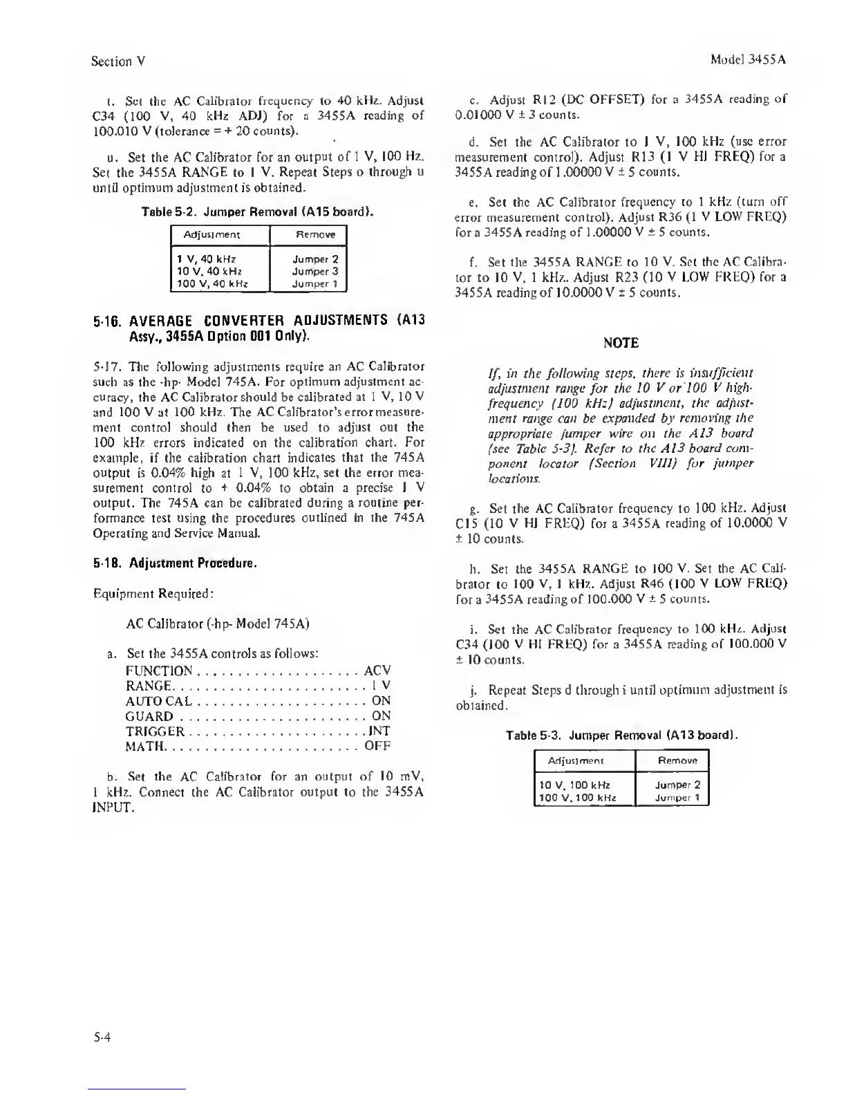
NOTE
If,
in the following
steps, there is insufficient
adjustment range
for
the 10 V or 100
V high-
frequency (100 kHz)
adjustment, the adjust-
ment range can be
expanded
by
removing
the
appropriate
jumper wire on the AI3 board
(see
Table 5-3). Refer to the AI3
board com-
ponent locator (Section VUIj
for
jumper
locations.
g.
Set the
AC
Calibrator frequency to 100
kHz. Adjust
CIS
(10
V
HI
FREQ) for a 3455A
reading
of
10,0000
V
±
10 counts.
h. Set the
3455A RANGE to 100
V. Set
the AC
Cali-
brator to 100
V. 1 kHz. Adjust R46 (100
V LOW FREQ)
for a
3455
A
reading of 1
00.000 V ±
5
counts.
i. Set the AC
Calibrator frequency to 100
kHz. Adjust
C34 (100
V HI FREQ) for a 3455A reading of
100.000 V
±
10 counts.
j.
Repeat Steps d through i until
optimum adjustment is
obtained.
Table
5-3.
Jumper Removal (A13
board).
Adjuttritent
Remove
10
V.
too kHz
100 V. 100 kHz
Jumper 2
Jumper 1
5-4
 Loading...


