170 Theory of operation ENWW
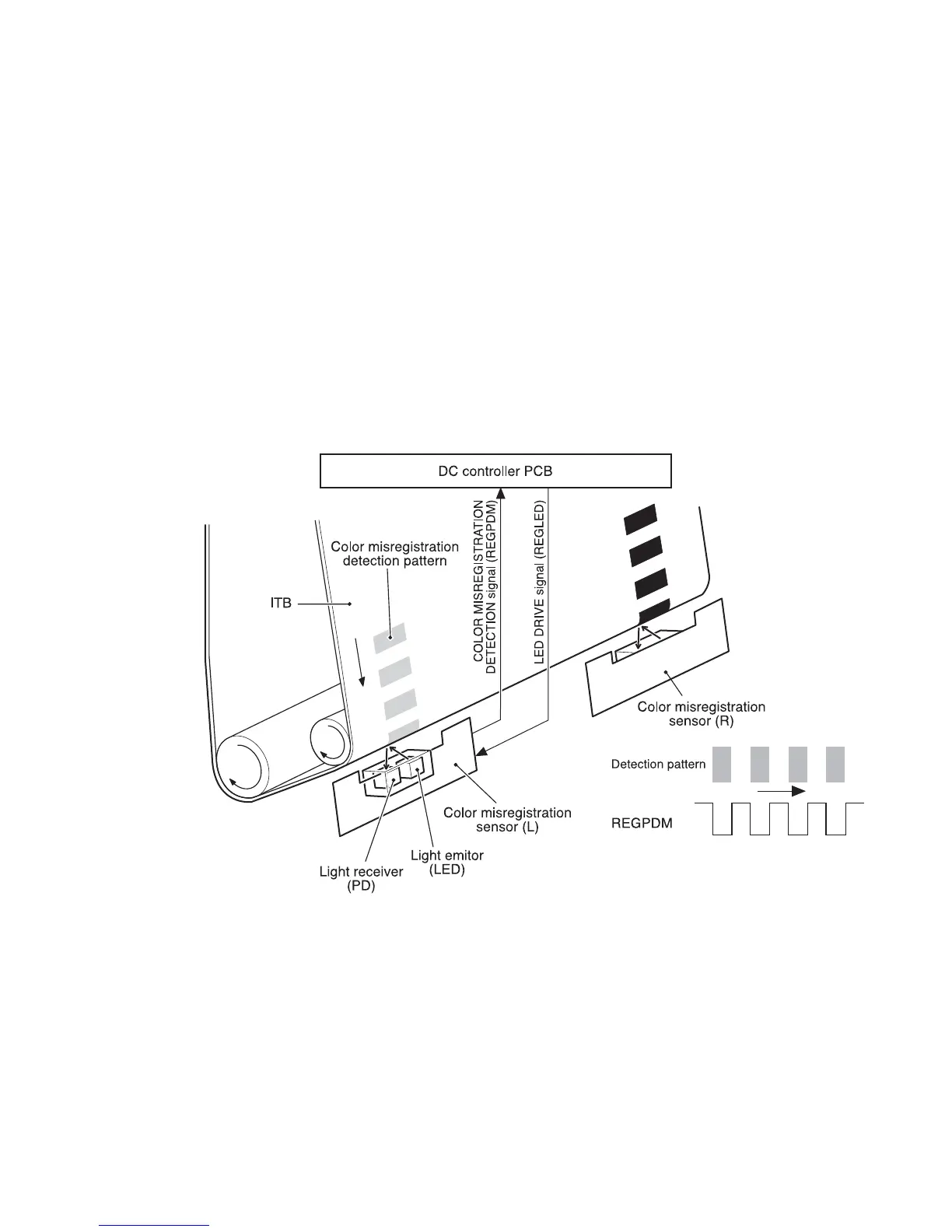
Color misregistration detection
This printer detects the positions of each color’s misregistration detection patterns formed on the
ITB to measure the misregistration.
The DC controller monitors the color misregistration sensors (PS12) during the foregoing color
misregistration control. There are two units of PS12 on the ITB, each having one light emitter
(LED) and one light receiver (PD).
The following is the sequence of this control.
1 The DC controller sends LED DRIVE signal (REGLED) and lets the LED emit light.
2 The light of the LED is reflected off the ITB and received by the PD on the sensor. The light
amounts received at the PD differ depending on whether or not the light is reflected from the
area the toner is on.
3 The light receiver converts the received light amount to voltage and sends it to the DC
controller in the form of the COLOR MISREGISTRATION DETECTION signal (REGPDM).
4 The DC controller detects the positions of the detection patterns according to the time the
REGPDM signals vary.
Figure 5-53 Color misregistration detection
The DC controller notifies the formatter of each error when the following errors are found during
color misregistration detection. The initial value is reset to the new color misregistration adjustment
value whenever an error occurs.
● Color misregistration sensor abnormality warning: No light is received at the light receivers.
● Color misregistration measurement out of range warning: The measurement is found to be out
of specified range.

 Loading...