TM 11-6625-1514-15
Section III
Paragraphs 3-1 to 3-9
SECTION III
OPERATING INSTRUCTIONS
3-1. INSTRUMENT TURN-ON.
3-2. The voltmeter is ready for use as received from
the factory and will give specified performance after a
few minutes warmup. See Section II for information
regarding connection to the power source and to the
voltage to be measured. Controls are shown in figure 3-1.
3-3. GENERAL OPERATING INFORMATION.
3-4. METER ZERO CHARACTERISTIC. When the
Model 400D and 400H Voltmeters are turned off, the
meter pointer should rest exactly on the zero calibration
mark on the meter scale. If it does not, zero-set the
meter as instructed in paragraph 5-7. The meter
supplied in the Model 400L Voltmeter is not provided
with a mechanical meter zero adjustment. When the
voltmeter is turned on with the INPUT terminals
shorted, the meter pointer may deflect upscale slightly;
this deflection does not affect the accuracy of a reading.
NOTE
When the voltmeter RANGE switch is set to the
lowest ranges and the INPUT terminals are not
terminated or shielded, noise pickup can be
enough to produce up to full-scale meter deflec-
tion. This condition is normal and is caused
by stray voltages in the vicinity of the instru-
ment. For maximum accuracy on the .001-volt
range, the voltage under measurement should
be applied to the voltmeter through a shielded
test lead.
3-5. METER SCALES. The two voltage scales on each
of the voltmeter models are related to each other by
a factor of 1 10 (10 db). In conjunction with the calib-
rated RANGE switch steps, this provides an intermediate
range step spaced 10 db between “power of ten” ranges,
which are 20 db apart. The relationship of the DECIBELS
scale to the 0 to 1 VOLT scale is determined by making
0 db on the DECIBELS scale equal to the voltage required
to produce 1 milliwatt in 600 ohms (0.775 volts). Thus,
the DECIBELS scale reads directly in dbm (decibels
referred to one milliwatt) across a 600-ohm circuit,
and can be used to measure absolute level of sine wave
signals. It can also be used to measure relative levels
of any group of signals which have the same waveform,
across any constant circuit impedance. The RANGE
switch changes voltmeter sensitivity in 10-db steps
accurate to within ± 1/8 db. The RANGE switch position
indicates the value of a full-scale meter reading.
3-6. CONNECTIONS. Voltmeter test leads must be
provided by the user. The type of leads and probes
used will depend upon the application, as listed below:
a For connection to low-impedance signal sources,
plain wire leads often are sufficient.
00102-2
b. For high-impedance sources, or where noise pickup
is a problem, low-capacity shielded wire must be used
with a shielded, dual banana plug for connection to the
voltmeter terminals.
c. If a probe is used, it should also be shielded to
prevent pickup from the hand.
d. For signals above a few hundred kilocycles, the
capacity of the test leads must be kept to a minimum
by using very short leads, preferably unshielded. An
alligator clip should be used at the test end so that
connection can be made without adding the capacity of
the user’s hands.
3-7. MAXIMUM INPUT VOLTAGE. Do not apply more
than 600 volts de to the INPUT terminals. To do so ex-
ceeds the voltage rating of the input capacitor.
3-8. If an applied voltage momentarily exceeds the
selected full-scale voltmeter sensitivity, a few seconds
may be required for circuit recovery, but no damage
will result.
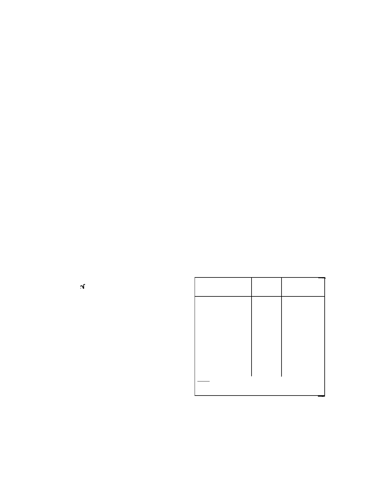
3-9. INPUT VOLTAGE WAVEFORM. The voltmeter
is calibrated to indicate the root-mean-square value
of a sine wave; however, meter pointer deflection is
proportional to the average value of whatever waveform
is applied to the input.
If the input signal waveform
is not a sine wave, the reading will be in error by an
amount dependent upon the amount and phase of the
harmonics present, as shown in figure 3-2 below.
When harmonic distortion is less than about 10%, the
error which results is negligible.
INPUT VOLTAGE
TRUE
RMS
METER
CHARACTERISTICS
VALUE
INDICATION
Fundamental = 100
100
100
Fundamental +10%
100.5
100
2nd harmonic
Fundamental +20%
102
100-102
2nd harmonic
Fundamental +50%
112
100-110
2nd harmonic
Fundamental +10%
100.5
96-104
3rd harmonic
Fundamental +20%
102
94-108
3rd harmonic
Fundamental +50%
112
90-116
3rd harmonic
Note: This chart is universal in application since
these errors are inherent in all average-respond-
ing type voltage-measuring instruments.
Figure 3-2. Effect of Harmonics on Voltage
Measurements
3-1

 Loading...


