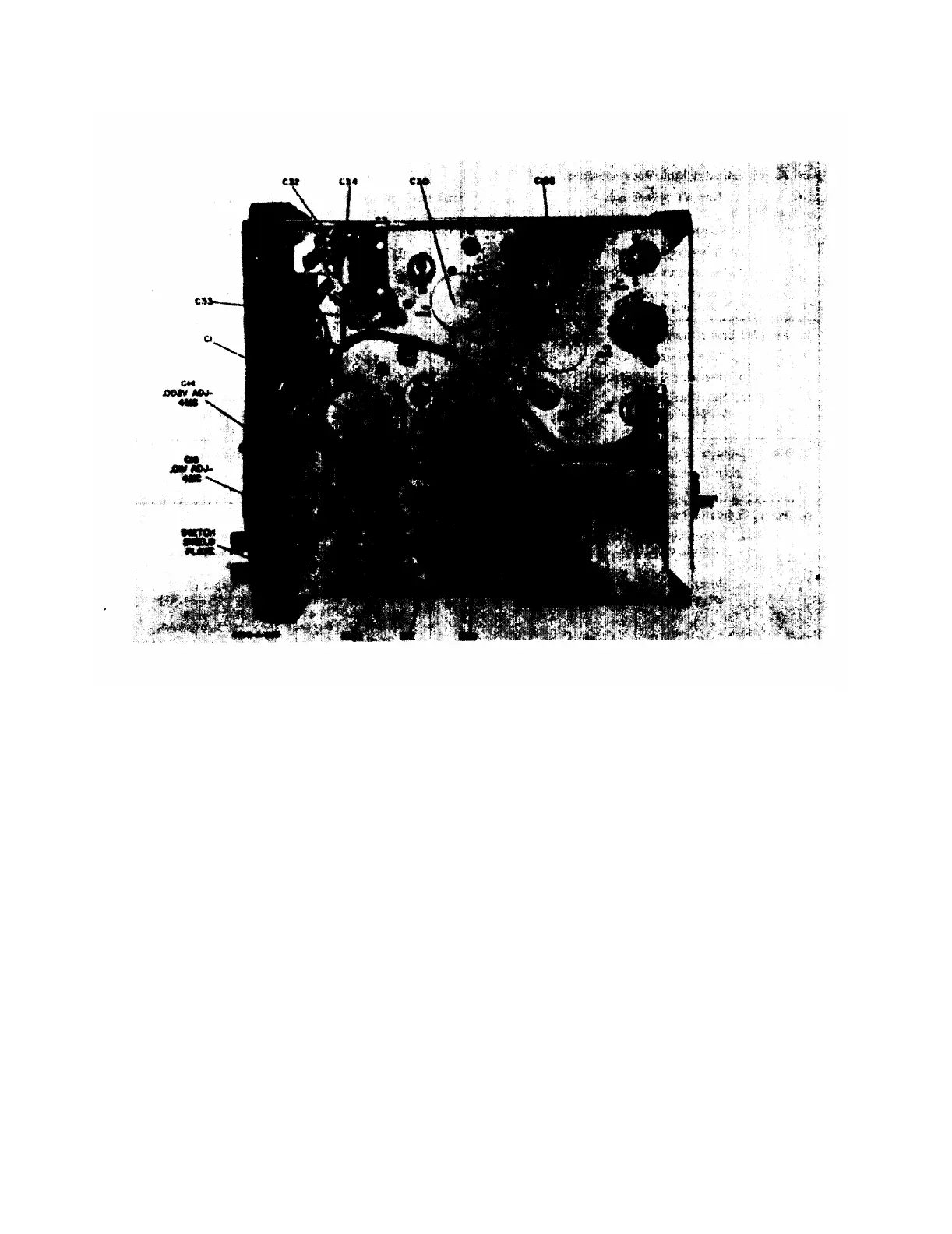
Figure 5-4. Right Side View of Voltmeter Chassis
TM 11-6625-1514-15
Section V
Paragraphs 5-22 to 5-23
a short circuit or partial short in the circuits of the
voltmeter amplifier section. A clip-on type milliam-
meter should be used for this measurement.
g. If the output voltage is stable but is incorrect,
measure the resistance of R62 and R64. The ratio
of these two resistors determines what the output voltage
will be. If the value of one of these resistors is in-
correct and produces the wrong output voltage, replace
it with a resistor which provides the correct output
voltage.
h. Measure the d-c voltage across C39A which must
be 12.6 volts with a line voltage of 115 volts. If nec-
essary, adjust R66 to obtain 12.6 volts. If the voltage
cannot be set to 12.6 volts, check the a-c voltage from
the associated transformer windings; also check CR3
and C39.
5-22. TESTING VOLTMETER PERFORMANCE.
5-23. The following test procedure checks the accuracy
and stability of the voltmeter at low and high frequencies
00102-3
and with low and high line voltages. It can be used for
comprehensive incoming inspection, for proof of per-
formance, and for trouble shooting. If the readings are
within specifications during these tests, the voltmeter is
operating properly. This test is made without removing
the cabinet. Instruments used to test the accuracy of
the voltmeter (see paragraph 5-5) must be known to have
sufficient
accuracy to make valid measurements. Proceed
as follows:
a. Connect the voltmeter as shown in figure 5-6.
(This setup measures calibration accuracy at mid-
frequencies.)
b. Set the line voltage to 115 volts, turn the voltmeter
on and allow a 30-minute warmup period.
c. Check the instrument meter zero setting as in-
structed in paragraph 5-7.
d Connect the voltmeter to the voltmeter calibrator;
set voltmeter RANGE switch to. 001, and set voltmeter
calibrator VOLTAGE SELECTOR switch to provide 0
volts output.
5-5

 Loading...


